8.4 Replacement of Major Parts
yyyy
yyyy
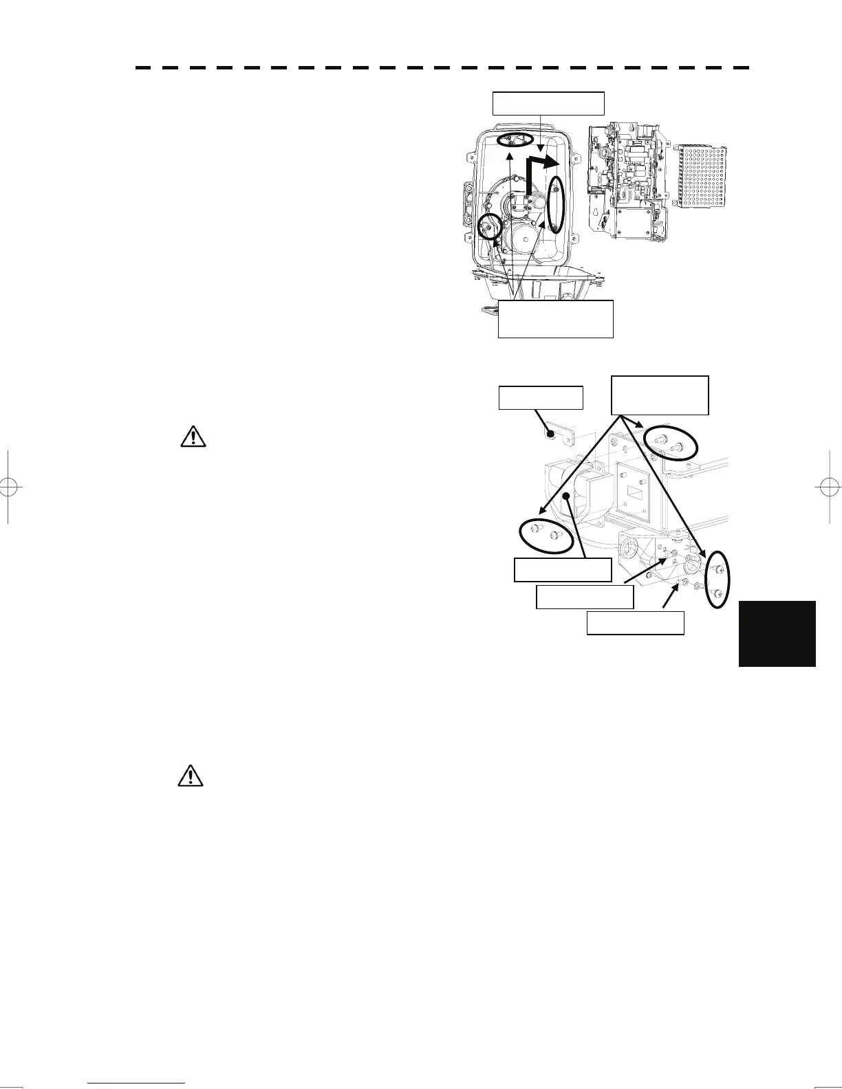
(4) Loosen the bolts (five M5 bolts) and remove the
transmitter-receiver unit. Slide the
transmitter-receiver unit upward to remove it.
Slide the unit.
Loosen the five
bolts.
(5) Remove the screws (six M4 screws) holding the
magnetron in place and replace the magnetron.
ut plate
Remove the six
screws.
Magnetron
Green cable
Yellow cable
Use a shielded secrewdriver because the contact of
the metal tool with the magnetron causes
deterioration of its performance.
8
(6) Cut the leads (yellow and green) for the replacement magnetron to an appropriate length, then tighten the
screws and fix the cables in place.
After having replaced the magnetron, reassemble the unit by following the disassembly procedure in the
reverse order.
Do not forget to tighten the bolts and screws, and do not forget to reconnect the cables.
Extreme care should be taken to connect the leads (yellow and green) to the magnetron for
prevention of contact with other parts or the casing. Contact may cause them to discharge.
8-20
 Loading...


