2.3 Functions of Software Buttons
yy
PPI
2
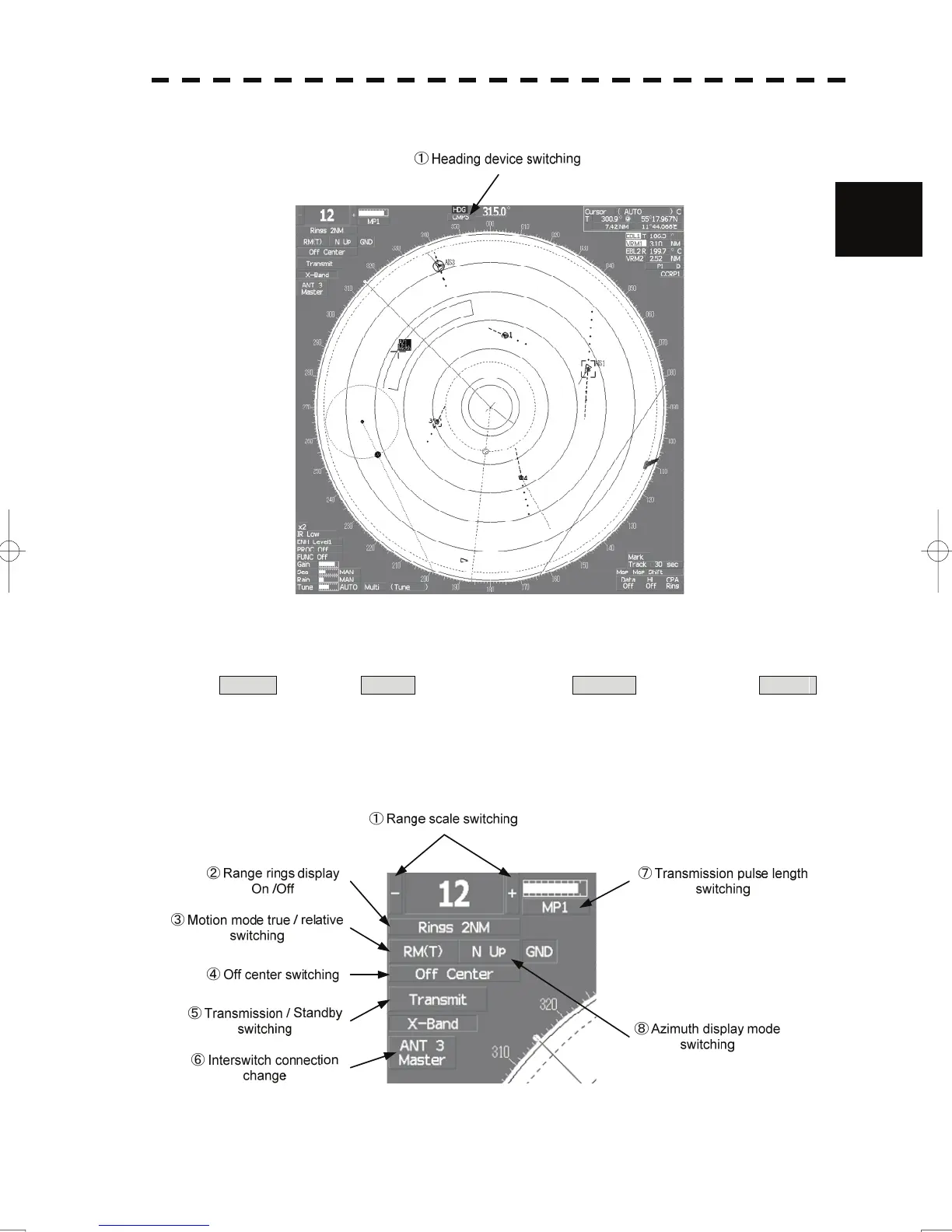
①:Heading device switching
This function switches the heading device.
GYRO (GYRO) ⇒ CMPS (Electronic compass) ⇒ G.COM (GPS compass) ⇒ GYRO
If the selected heading device is not connected to the equipment, an alarm is issued.
Upper left of the display
2-16
 Loading...


