JMA-9100 Instruction Manual > 8.COUNTERMEASURE FOR TROUBLE ... > 8.4 REPLACEMENT OF MAJOR PARTS
8-25
8
Adjust the setting in the service engineer menu until the tuning indication bar on the
display unit reaches the 8th calibration marking.
Check in the service engineer menu that the magnetron current is between the 6th and
9th calibration markings.
4) Finally, initialize the transmission time in the service engineer menu.
8.4.2.5 Transmitter Receiver Unit NTG-3225
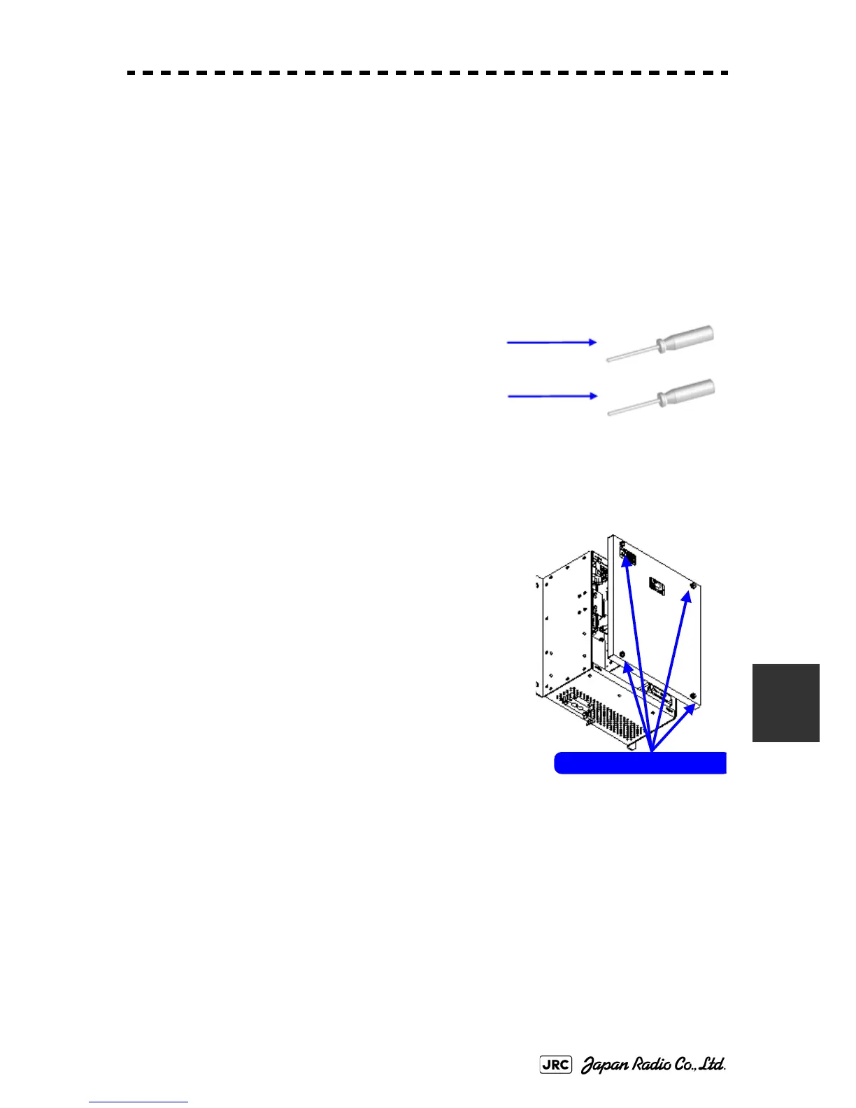
[Required tools]
A flatblade screwdriver for 6 mm screws
・A Phillips screwdriver for 4 mm screw
[Replacement procedure]
1) Loosen the four screws and remove the cover.
The screws are slotted captive screws.Use a flatblade
screwdriver.
Loosen the four screws .

 Loading...


