JMA-9100 Instruction Manual > 8.COUNTERMEASURE FOR TROUBLE ... > 8.4 REPLACEMENT OF MAJOR PARTS
8-15
8
8.4.2.1 Scanner Unit NKE-1130
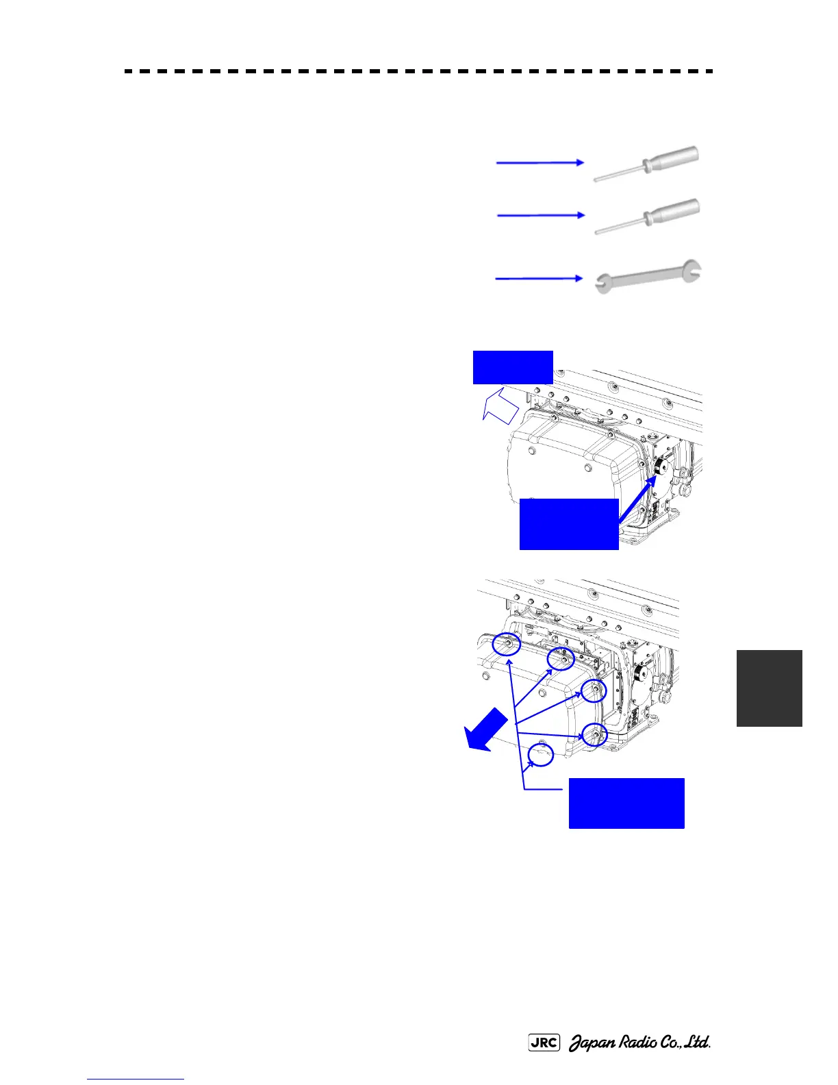
[Required tools]
•
A Phillips screwdriver for 4 mm screw
•
A Phillips screwdriver for 6 mm screw
•
A wrench (width across flats 13 mm, for M8 screws)
[Replacement procedure]
1) Before starting part replacement work, turn
off the safety switch of the scanner unit.
The safety switch is located on the rear (stern)
side. Remove the cover and turn off (to the
lower side) the safety switch.
2) Remove the pedestal cover.
Make sure that there is no foreign matter or
dust adhered to the gasket when you put the
cover on.
Bow side
Turn off the
safety switch.
Remove the eight
hexagonal screws.
Removing the port side cover
 Loading...


