8-16
JMA-9100 Instruction Manual > 8.COUNTERMEASURE FOR TROUBLE ... > 8.4 REPLACEMENT OF MAJOR PARTS
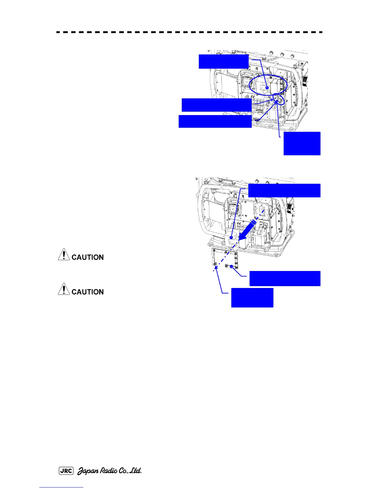
3) Remove the cover on the left (port)
side and check that there is no
remaining electric charge between
J2101 pin 1 and J2101 pin 3 in the
modulation circuit board CPA-
264. (Multimeter requires
DC1000V input capability).
Remove the two screws (M4)
holding the magnetron cables
(both yellow and green).
4) Remove the eight screws (M6) to
remove the fixture holding the
magnetron. The screws cannot be
removed from the fixture, so loosen the
all eight screws and remove the
magnetron together with the fixture.
The magnetron is held by a hook, but be
careful not to let it fall.
Use a non-magnetic screwdriver. If the
magnetron comes into contact with any
metal (tool), its performance may
deteriorate.
5) Install the new magnetron together with the fixture and tighten the screws to hold the
cables.
Follow the removal procedure in the reverse order.
Do not forget to tighten the screws and connect the cables.
[Operation check]
After you have completed the replacement work, follow the procedure below to
check the operation.
Magnetron
Remove the yellow cable.
Remove the green cable.
Remove the
two screws.
Remove the magnetron.
Remove the metal fixture.
Loosen the
eight screws.
 Loading...


