JMA-9100 Instruction Manual > 8.COUNTERMEASURE FOR TROUBLE ... > 8.4 REPLACEMENT OF MAJOR PARTS
8-27
8
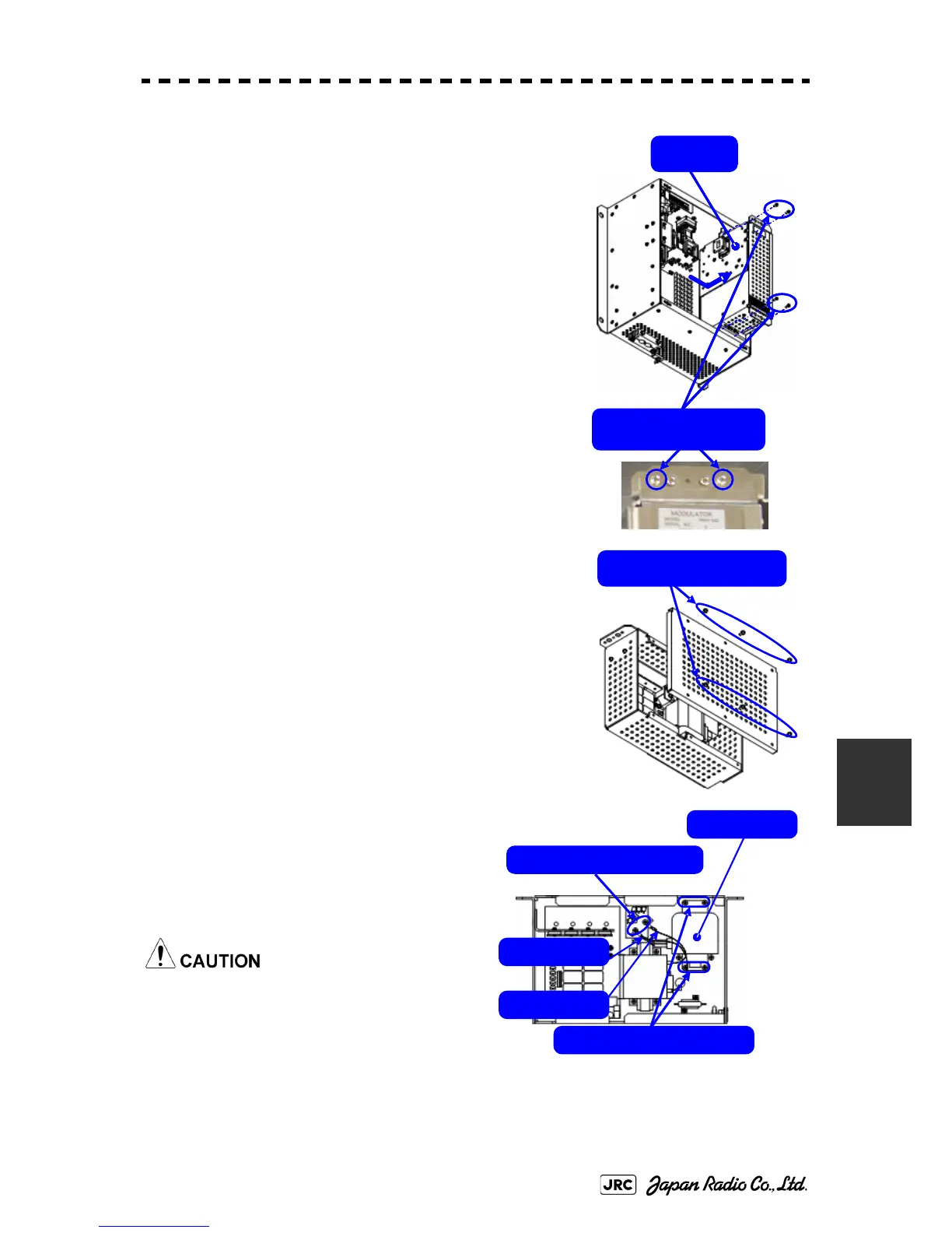
4) Remove the cables connected to the modulator and
the screws on the outside of the modulator (four M4
screws) and slide the modulator to the right to remove
it.
5) Remove the screws (six M4 screws) and take off the
modulator cover.
6) Remove the screws holding the cables
(two M4 screws) and the screws holding
the magnetron (four M4 screws) and
remove the metal fitting and the
magnetron.
Use a non-magnetic screwdriver. If the
magnetron comes into contact with any
metal (tool), its performance may
deteriorate.
Remove the four
outside screws.
Modulator
Remove the six screws.
Remove the four screws.
Magnetron
Remove the two screws.
Green cable
Yellow cable

 Loading...


