16-21 Section 16 Failures and After-Sale Services
Radar Failure Checklist
[Important] Before ordering a repair, please check and fill in the following items and then contact the
applicable repair office.
If there are unknown items, please contact the ship and fill in as accurate as possible.
Ship Name: ___________________ Phone: _____________ Fax: __________________
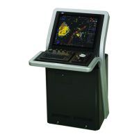
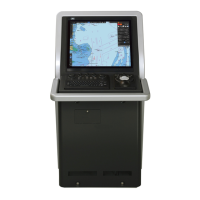
Integrated Radar Model Name: JMR- ___________________ Serial Number: ________________
(Please fill in all digits accurately.)
(1) Check the following items sequentially and circle either YES or NO for each item.
If none is applicable, please write down the specific reason in No. (18) Other description.
(2) If any of check items (1) through (5) is NO, please check the fuses of the equipment. (See "16.1.3
Fuse inspection.")
(3) Check items (4) through (17) with transmission (TX) ON.
* It may not be possible to use (14), (15) and (17) unless options and external devices are not
connected; if they are not connected, it is not necessary to answer these items.
No. Check Item Result
(1) The power turns On. (The light of the operation unit illuminates.) YES NO
(2) The unit is placed in the standby state several minutes after turning the power
On.
YES NO
(3) When the power is turned On (or transmission On), something is displayed on
the LCD/LED monitor. (Illuminates)
YES NO
(4) When transmission (TX) is turned On, the Radar antenna rotates. (Check all of
the following items with transmission On.)
YES NO
(5) Magnetron current flows. (See the Instruction Manual.) YES NO
(6) Tuning can be performed. (Check in a range of 6NM or above.) YES NO
(7) Fixed markers are displayed. YES NO
(8) The VRM is displayed. YES NO
(9)
White noise is displayed with minimum Sea and Rain, maximum Gain, IR-Off
and range 48NM.
YES NO
(10) Target reflection echoes are displayed, YES NO
(11) The sensitivity of reflection echoes is normal. YES NO
(12) The EBL is displayed. YES NO
(13) The cursor symbols move. YES NO
*(14) The GYRO course can be set up and is displayed normally. YES NO
*(15) The LOG speed is displayed normally. YES NO
(16) The target tracking function operates normally. YES NO
*(17) If the straight mode (II) is switched to the cross mode (X) when an interswitch is
provided, the failed (NO) items in (1) through (16) above are swapped between
the right and left display units.
YES NO
(18) Other description (error messages, etc.)
 Loading...