6 Parameter level
32
Factory settings are shown bold.
Parameter display independent of the controller type:
Ö Chapter 7.2 „Controller“
Decimal places for some parameters depend on the device setting:
Ö Chapter 7.8 „Display/Operation/Service counter“
Cycle time of
output
CY1
0.0…
20.0…
999.9s
For a switching output, the cycle
time should be selected so that, on
one hand, no inadmissible process
value fluctuations are generated
caused by the cycled energy supply
and, on the other hand, no overload
of the acutators occurs.
CY2
1)
0.0…
20.0…
999.9s
Dead band
db
0.0…
999.9
Spacing between the two control
contacts of the 3-state controller and
the modulating controller
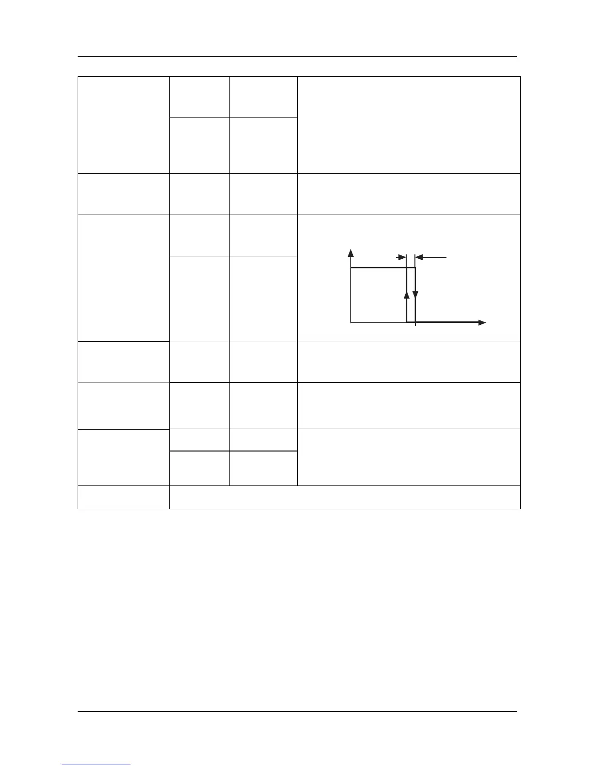
Hysteresis
HyS1
0.0…
1.0…
999.9
Hysteresis for switching controller
with Pb1,2 = 0.
HyS2
1)
0.0…
1.0…
999.9
Valve
run time
tt
5…60…
3000s
Used run time range of the control
valve (actuator) of the modulating
controller
Operating
value
Y0
-100…
0…
+100%
Output value for P and PD
controllers
(for x=w is y=Y0)
Output value
limits
Y1
0…100% Maximum output value limit
Y2
-100…
+100%
Minimum output value limit
(Only effective when Pb>0!)
1) For 3-state controllers only (controller output 2)
100%
y
xw
HyS1, 2
0%
 Loading...