11
2 Installation - Electrical Connection
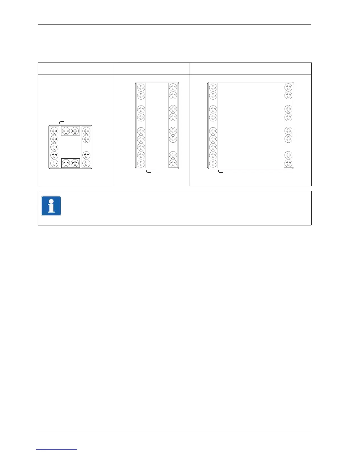
2.6 Connection diagram
The terminal strips on the device rear are equipped with screw terminals. Please refer to the tech-
nical data for specifications concerning the conductor cross section.
LC100 LC200 LC300
TIP!
The USB interface (socket Mini-B, 5-pole) is labeled on the device with "SETUP“
and is located on the case top of the LC100 and on the case bottom of the LC200
and LC300. It is used for connection to a PC that is running the setup program.