the FXS interface. An FXO interface is a two-wire interface; the leads are called the tip (T) and the ring
(R).
You can interconnect the following voice applications with CESoPSN bundles:
•
Analog 4WE&M voice applications using the 4WE&M interface module
•
Digital voice applications using the T1/E1 interface module
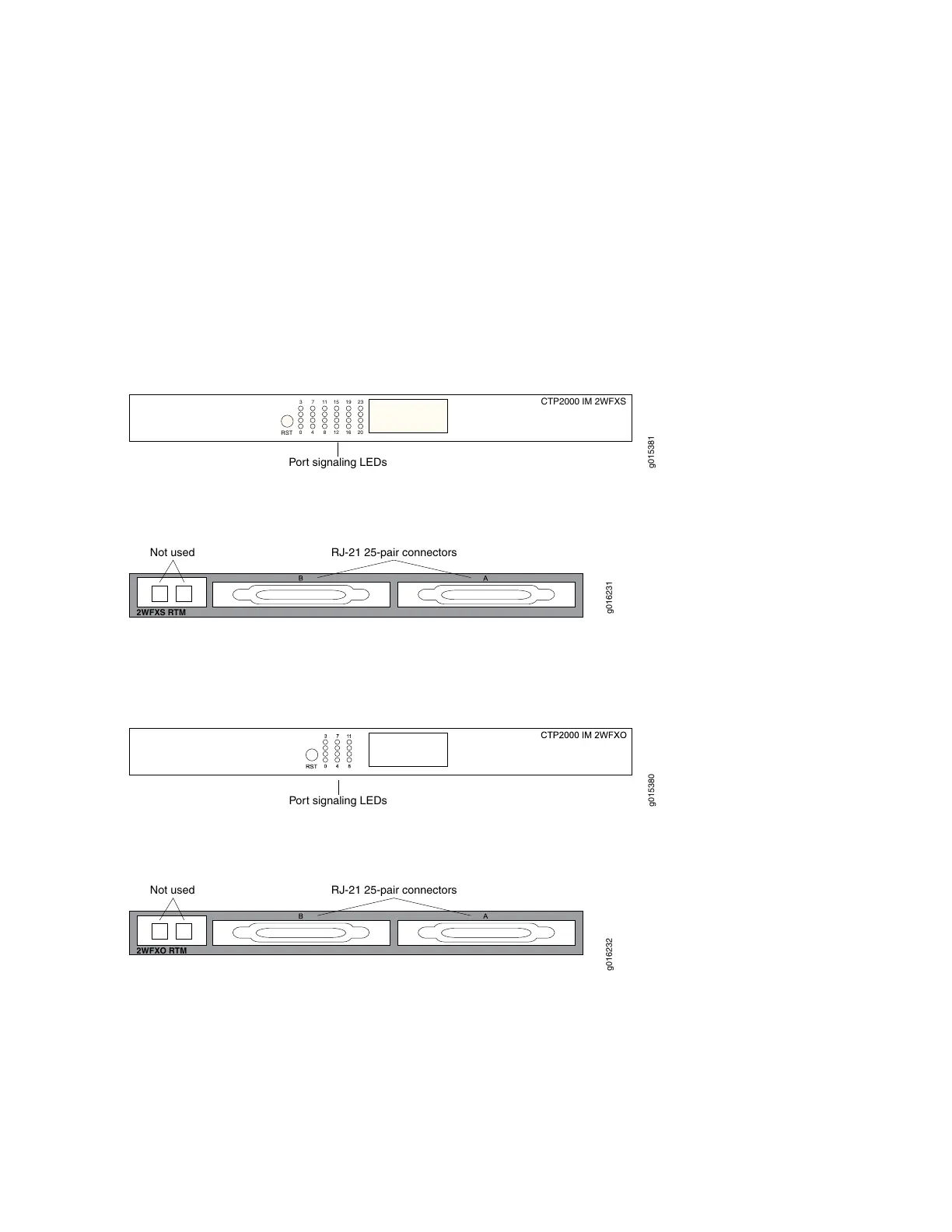
Both interface modules consist of a front module and an RTM. See Figure 20 on page 21 and
Figure 21 on page 21 for the CTP2000 2W-FXS interface module.
Figure 20: Front Panel of CTP2000 2W-FXS Interface Module
RST
2016
128
40
231915
11
73
CTP2000 IM 2WFXS
Port signaling LEDs
g015381
Figure 21: Rear Panel of CTP2000 2W-FXS RTM
Not used
RJ-21 25-pair connectors
2WFXS RTM
g016231
See Figure 22 on page 21 and Figure 23 on page 21 for the CTP2000 2W-FXO interface module.
Figure 22: Front Panel of CTP2000 2W-FXO Interface Module
Port signaling LEDs
g015380
Figure 23: Rear Panel of CTP2000 2W-FXO RTM
Not used
RJ-21 25-pair connectors
2WFXO RTM
g016232
Both modules use connector A on the RTM. For both modules, connector B and the RJ-45 connectors are
not used. See “CTP2000 FXS and FXO Interface Module Cables and Pinouts” on page 48 for connector
pinout information.
You set the signaling by using the software on both modules. You cannot reconfigure the jumper parameters.
21