14
Installation - continued
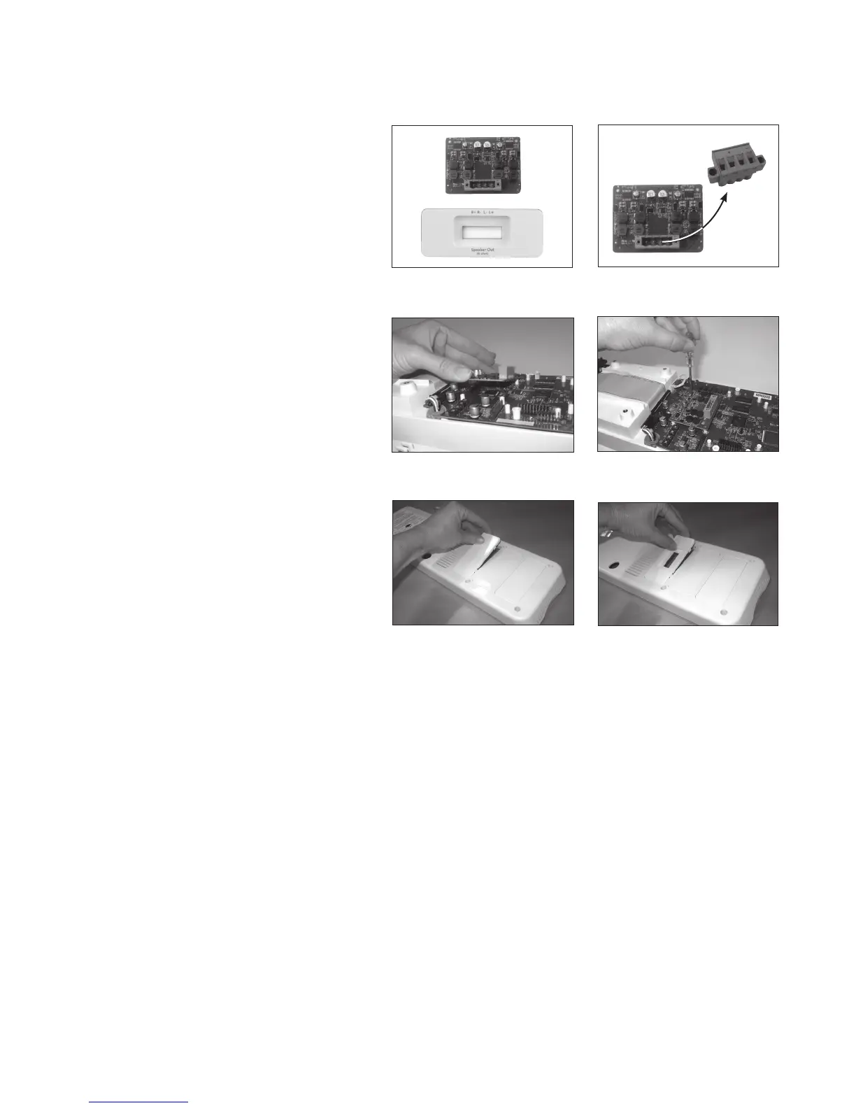
4. Remove the module and access panel
from the packaging. (See Image 4)
NOTE: Handle by edges to minimize
chance of electrostatic discharge.
5. Remove terminal block from the module.
(See Image 5)
6. Connect the 10 pins on the Page
Override module to the 10-pin connector
on the main Tower PCB. Make sure the
pins are all aligned properly and that the
module board is seated all the way down.
(See Image 6)
7. Attach the board to the main Tower PCB
using the four included screws.
(See Image 7)
8. Remove the access panel cover from the
back panel and replace with the Speaker
Expansion module access panel.
(See Image 8 & 9)
9. Replace the back panel and screws.
10. To connect speakers, see page 29.
Image 4
Image 6
Image 7
Image 8
Image 9
Image 5