32
Installation - continued
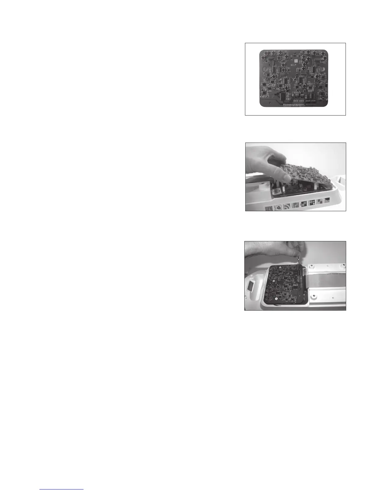
4. Remove the module from the packaging. (See Image 4)
NOTE: Handle by edges to minimize chance of electrostatic
discharge.
5. Connect the 2 pins on the Channel expansion module to the 2-pin
connector and then angle the module down to connect to the
30-pin connector. Make sure the module board is seated all the
way down and make sure no pins are exposed. (See Image 5)
6. Attach the module to the Tower PCB using the four included
screws. (See Image 6)
7. Replace the back panel and screws.
8. Turn on the Juno Tower and verify that the module has been
detected by navigating to the Microphone Volume menu on the
LCD. Confirm that channels C-E are available.
9. Test with microphones using channels C through E.
See Programming Microphones in the Juno User Guide.
Image 6
Image 5
Image 4