10
b
a
e
c
d
b
a
d
c
d
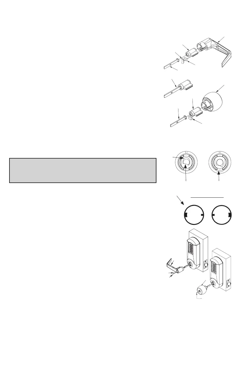
G-3 Assemble the required tailpiece (d) (supplied) with
your KIL/KIK cylinder. All tailpieces must be
installed vertically (with key removed from
cylinder) for proper installation.
G-4 Insert the KIL/KIK cylinder (a) into the outside
lever/knob (b) and secure it with the cylinder
retainer (c) and lever insert (e) (no insert on
knobs). The KIL/KIK cylinder should be snug
and unable to move freely.
H. INSTALLING / REMOVING OUTSIDE LEVER/KNOB
(Key-In-Lever/Knob models only)
Note: Installing lever/knob to the unit assemblies
before mounting the unit assemblies may ease initial
installation.
H-1 Make certain the lever catch is up as shown (c).
The lever catch should be flush around the outer
diameter of the outside driver. Make certain the
lever sleeve (f) is rotated to properly mate with the
outside lever/knob.
H-2 Insert one of the supplied keys (a) into the
outside lever/knob cylinder (b) and rotate key
counterclockwise 45 degrees.
H-3 Insert the outside lever/knob (b) until it is flush to
the outside unit assembly (levers fit closer than
knobs). Secure the outside lever/knob by rotating
the key clockwise 45 degrees to the horizontal position.
Remove key.
LH
KIL Lever Sleeve
RH
f
b
b
a
a
45º
c
Correct
Position
Incorrect
Position
 Loading...