Do you have a question about the Kaba 5 00 Series and is the answer not in the manual?
Mark door for holes using template and drill specified holes.
Mortise door edge for latch faceplate according to dimensions shown.
Secure latch unit to the door with combination screws, ensuring flush fit.
Identify door hand (left or right) to proceed with installation steps.
Rotate drive unit 180 degrees to reverse handing for right-hand doors.
Adjust connecting screws and remove spacer for thinner doors (13/8" to 11/2").
Add extra spacer and use same screws for thicker doors (21/8" to 21/4").
Insert drive unit into cross bore hole, ensuring latch bolt and red collar seat correctly.
Ensure drive unit engages latch prongs and shoe retractor engages tailpiece.
Slide drive hub into sleeve and guide red collar through mounting hole.
Choose LectroBolt length based on door thickness using the provided chart.
Insert LectroBolts through housing, partially tighten, then secure all mounting bolts.
Insert inside lever/knob onto unit assembly and secure with set screw using Allen wrench.
Remove cylinder by disassembling lever sleeve, cylinder insert, and retainer.
Select the appropriate tailpiece from the chart for your KIL/KIK cylinder.
Vertically assemble tailpiece to cylinder, ensuring alignment with the core.
Insert KIL/KIK cylinder into lever/knob and secure with retainer; ensure snug fit.
Ensure lever catch is up and flush, and lever sleeve is rotated for proper mating.
Insert key and rotate counterclockwise 45 degrees to prepare for installation.
Insert lever/knob until flush, then rotate key clockwise 45 degrees to secure.
Insert key, rotate, insert release tool, push lever catch, and remove lever/knob.
Ensure lever catch is up and flush; lever sleeve must mate correctly with the outside driver.
Insert lever/knob until flush, then use release tool to slide lever catch down to lock.
Insert tailpiece vertically into lever/knob, ensuring alignment with the interchangeable core.
Remove the interchangeable core first, then detach the tailpiece.
Insert release tool into hole, push lever catch, and remove outside lever/knob.
Tailpiece must be prepped for desired length for ASSA/Medeco/Yale cylinders.
Locate score mark matching cylinder prep and break tailpiece accordingly.
Use pliers to break tailpiece to desired length at score marks.
Insert Medeco tailpiece vertically, align with cylinder, and insert cylinder into lever.
Connect cable, place battery pack in cover, and secure cover with security screws.
Remove battery cover screws using the security screw tool to access batteries.
Remove old batteries and insert four new Alkaline AA batteries in correct orientation.
Reconnect battery cable, place holder in cover, and screw back cover securely.
Check if inside latch retracts when lever is held and extends when released.
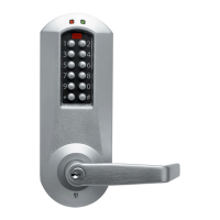
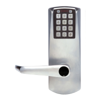
Enter factory code 12345678; check for green light, tone, and motor sound.
Check if outside latch retracts when lever is held and extends when released.
Test key function: rotate counterclockwise to retract latch, clockwise to extend.
Change factory master code to program lock; refer to Operation Manual for details.
Select 'Entry Lock with Passage' option during setup for Standard Software.
Select appropriate lock type using Enerprise Software during lock setup.
Mark strike location on door frame, ensuring opening aligns with latch bolt.
Mortise doorframe to dimensions and secure strike with combination screws.
Check deadlatch rests on strike plate and inspect for gaps between door and frame.
Mark locations with approximately 3/16" (5 mm) gaps for bumper placement.
| Brand | Kaba |
|---|---|
| Model | 5 00 Series |
| Category | Door locks |
| Language | English |