14
B-8 Check the bevel of the mortise faceplate. If adjustment is required, loosen
the two bevel screws and adjust mortise front plate angle to match the
bevel of the door (R).
B-9 Re-tighten screws.
B-10 Install the mortise with two 1" Phillips screws (Q) provided.
B-11 Install mortise faceplate (P) with the two 8-32 x
1
⁄4" screws provided.
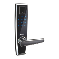
C. INSTALLING THE STRIKE
C-1 Align the paper template on the door
frame to match with the desired handle
height, and along the vertical center line of
the mortise (CL), which is also the center
line of the door, allowing for any bumpers
on the door frame.
Respect applicable building codes regard-
ing handle height.
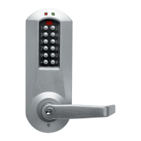
C-2 Select the strike for the desired handing,
according to the depiction on the template.
Mark the location of the strike cutout and
mounting screws.
C-3 Drill pilot holes for the strike mounting
screws. Mortise the door frame for the
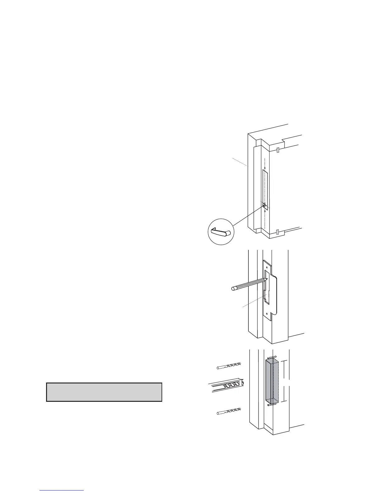
strike dimensions shown.
3
3
⁄8" (L) X 1" (D) X 1" (W)
Note: Make certain not to mortise
over screw holes drilled earlier.
(
C
L
)
Strike
Cutout
3
3
⁄8"