Page 23 KACO blueplanet 3.0 NX3 M2 KACO blueplanet 5.0 NX3 M2 KACO blueplanet 8.0 NX3 M2 KACO blueplanet 10.0 NX3 M2
KACO blueplanet 15.0 NX3 M2 KACO blueplanet 20.0 NX3 M2
7.8 Connecting the Smart-Meter for dynamic feed
If you want to implement the function dynamically, you need to install the Smart-Meter. The communication unit is only
compatible with the Eastron Smart-Meter (SDM630 – Article No. 3015600 is available via our customer service).
NOTE
The Smart-Meter must support the MODBUS protocol and communicates with baud rate 9600, parity
“None”, Stop-Bits “1”
Ensure that individual wires at the terminal contact of the Smart-Meter are attached with the correct
torque and cannot work loose. Attach protective cover if fitted.
NOTE
Damage to the inverter from electrostatic discharge
Components inside the device can be damaged beyond repair by electrostatic discharge.
› Ground yourself before touching a component.
NOTE
A network cable of category 5E or higher is required for connection to the RJ45 socket. A network cable
with good resistance to UV radiation is also required for use outdoors.
The RS485 connection can support communication with a maximum installation length (across all inverters)
of 1000 m. The individual and control connected must be measured in accordance with EMC requirements
EN 62920 if the length of the cable attached at the signal and control connection is more than 30 m
according to the standard.
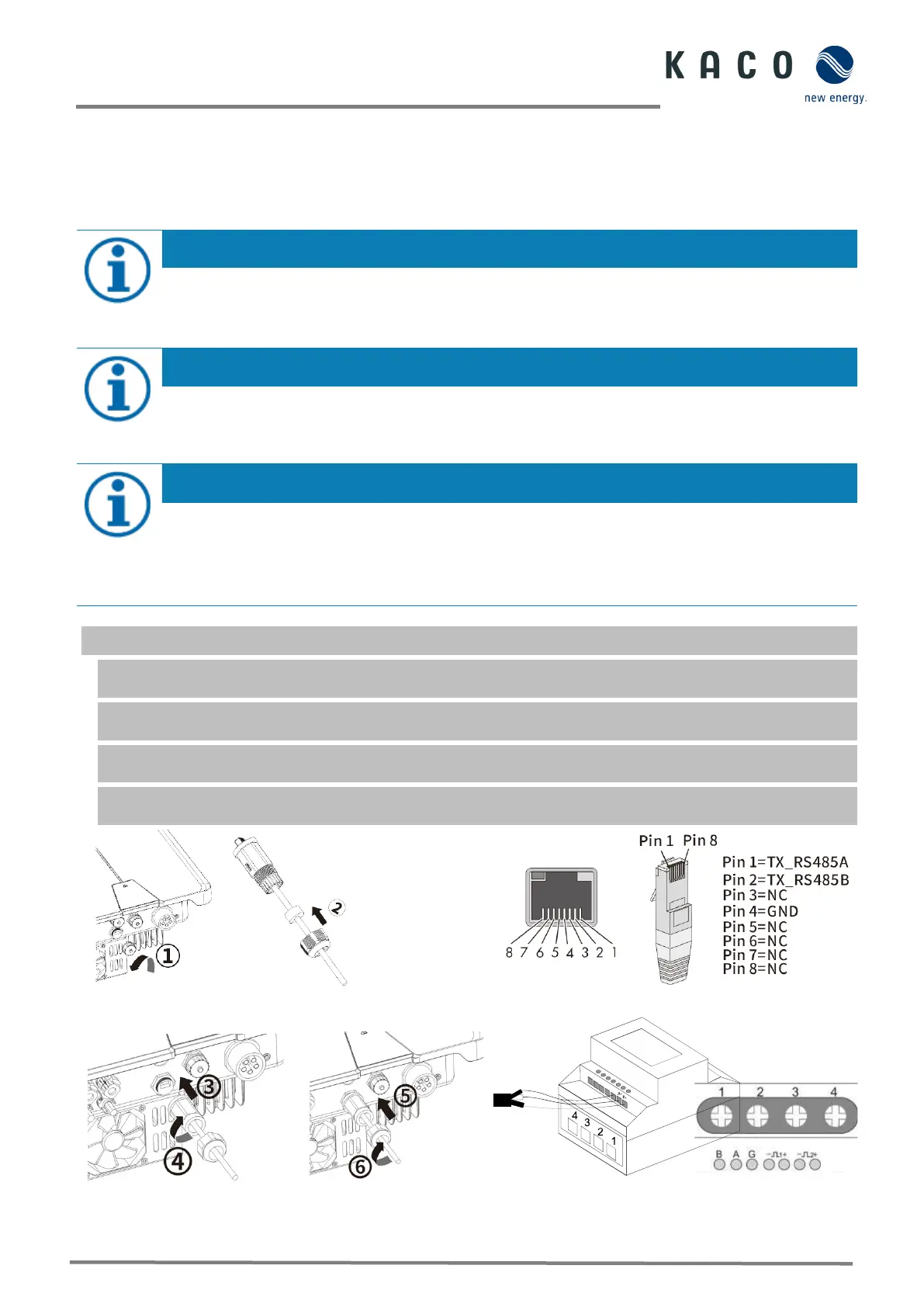
Fig. 34. Configure network connector
Fig. 35. Cable pin assignment
Fig. 36. Insert the network cable
Fig. 37. Network cable on the Smart-Meter
(at top of housing - information in the Smart-Meter
» RS485 connection established. Lay signal cable correctly.
The device and the Smart-Meter have been firmly installed on a mounting bracket.
1. Unscrew the cover cap (Pos. 1 in Fig. 34 ) of the communication connection and route 8-pin network cable through
the enclosed thread sleeve, forcing nut and seal (Pos. 2).
2. Strip the insulation from the network cable and crimp copper wire to the corresponding terminal (in accordance
with DIN 46228--4, provided by the customer) of the standard network connector (RJ45) (see Fig. 35).
3. Insert network connector into the communication connection of the device (Pos. 3/5) and tighten the thread
sleeve. Then tighten the forcing nut (Pos. 4/6) (see Fig. 36. )
4. Fit wire sleeve to the other end of the cable and connect to the contacts of the Smart-Meter. Screwdriver type:
PH0, tightening torque: 0.7Nm (See Fig. 37)
 Loading...