Page 19 KACO blueplanet 3.0 NX3 M2 KACO blueplanet 5.0 NX3 M2 KACO blueplanet 8.0 NX3 M2 KACO blueplanet 10.0 NX3 M2
KACO blueplanet 15.0 NX3 M2 KACO blueplanet 20.0 NX3 M2
Number of modules per string:
max
: per string < 0.6 * max. recommended PV generator
power
max
: per string < 0.6 * max. recommended PV generator
power on the MPP tracker used < max. power per MPP
tracker
MPP tracker A+B together < max. recommended PV
generator power
Imax: Depending on PV generator
The input current from Chapter 4.1 on page 7 is different for each MPP tracker and must not be exceeded. Therefore,
pay close attention to whether this value applies to PV1 or PV2.
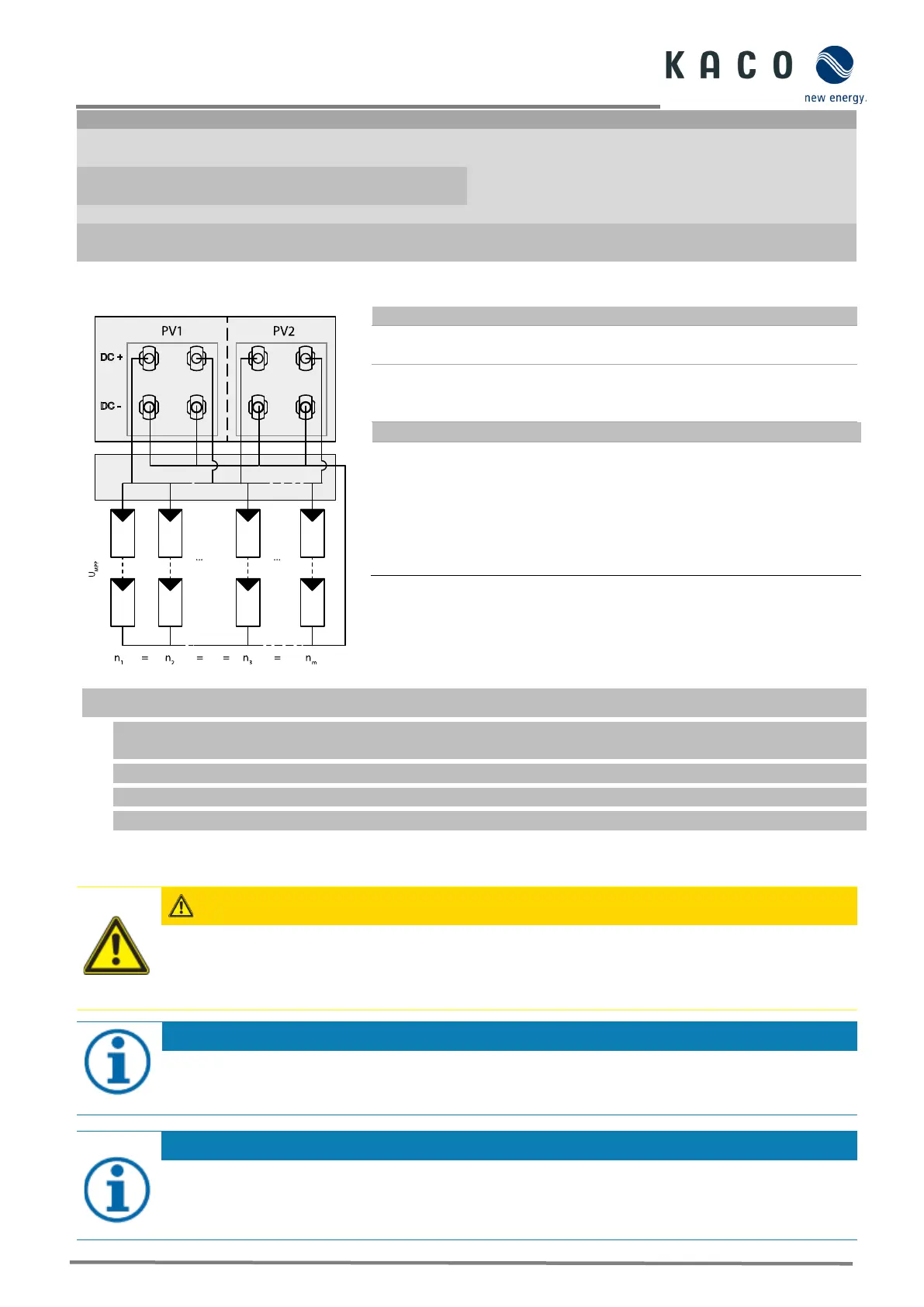
7.5.4 Connection in parallel operation
Both MPPTs must be connected individually to the generator junction
box.
The DC inputs can therefore also be connected in parallel.
Only lines with the same MPP voltage may be connected in parallel
Number of modules per string:
If the MPP trackers are used in parallel operation, the maximum
permissible power is 1.1 times the nominal power. In addition, the
maximum MPPT current is limited by the lowest value of all MPPTs.
For example, if the 15 kW inverter is used in parallel operation, the
maximum permissible power is 1.1x 15 kW = 16.5 kW and each MPPT
current is limited to 20 A (since one MPPT is rated for 32 A and the other
Fig. 24. Recommended connection in parallel operation for blueplanet 20.0 NX3
Open the corresponding “KACO NX Setup” APP for this device.
1. Select <Select inverter> in the <Communication unit> menu and view the <Enable/disable functions> via the
<Settings for> menu.
2. Enable the <MPPT parallel operation> function. (See Fig. 94 on page 42)
3. An external string fuse must be installed.
» Parallel operation is enabled.
7.5.5 Designing the PV generator
CAUTION
Damage to components due to faulty configuration!
In the expected temperature range of the PV generator the values for the no-load-voltage and the short
circuit current must never exceed the values for U
dcmax
and I
scmax
in accordance with the technical data.
› Observe limit values in accordance with the technical data.
Type and configuration of the PV modules
Connected PV modules must be dimensioned for the DC system voltage in accordance with IEC 61730 Class
A, but at least for the value of the AC grid voltage.
Dimensioning the PV generator
The device is designed with a reserve of DC short-circuit current resistance. This allows for oversizing of the
connected PV generator. The absolute limit for the PV generator is the value of the max. short-circuit
current (lsc max) and the max. no-load voltage (Uoc max).

 Loading...