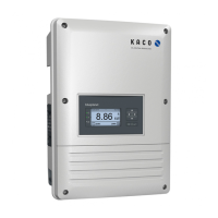
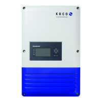
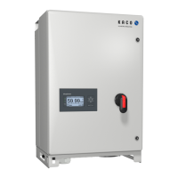
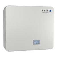
Page 29 KACO blueplanet 3.0 NX3 M2 KACO blueplanet 5.0 NX3 M2 KACO blueplanet 8.0 NX3 M2 KACO blueplanet 10.0 NX3 M2
KACO blueplanet 15.0 NX3 M2 KACO blueplanet 20.0 NX3 M2
9.6 Connecting to the device
9.6.1 Connecting to the device for the first time
WLAN of your mobile device is enabled
and any existing customer WLAN network
router is switched on.
Note: The initial connection is generally made
via a hotspot.
The “KACO NX Setup” APP from the
Android/iOS Store has been installed and
opened on your mobile end device.
The communication unit is connected to
the COM3 port of the device. (see Chapter
7.7 on page 21)
Note: Each device in the device series must be
configured with the enclosed communication
unit. Thereafter there is a fixed assignment to
The access details for your / your
customer’s WLAN network are to be made
available to the solar installer.
2. Grant authorisation for use of images,
videos and camera.
3. Scan the QR code on the communication
unit. Max. distance from the scan frame
shown in the scan window. See Fig. 43
» The connection to the hotspot WLAN is
established (B…).
Fig. 42. Select <Commissioning>
Fig. 43. Scan QR code on
communication unit
• Communication unit not mounted correctly or defective, or RS485 interface
of the inverter defective.
device
3 Standby self-test
The white “SOLAR” LED is illuminated when AC and DC voltage is present. The
device performs a self-test.
After flashing, the device is ready for feed-in.
3 Feed-in operation
The white “SOLAR” LED is illuminated when the device is feeding into the grid.
The LED is off when there is no feed-in.
4 COM
The white “COM” LED is illuminated during communication (data logger,
Smart-Meter, communication unit) and during a firmware update via RS485.
The LED is not illuminated if the communication is interrupted or non-
existent.
5 Fault
The red “Fault” LED lights up due to an error and the feed into the grid is
interrupted. The corresponding error code is displayed in the KACO NX Setup
APP in the Live values menu
Fig. 61 on Page 38. If there is no fault, the LED
goes out.
1-5 Offline
There is no AC/DC supply to the device.
 Loading...
