KACO blueplanet 3.0 NX3 M2 KACO blueplanet 5.0 NX3 M2 KACO blueplanet 8.0 NX3 M2 KACO blueplanet 10.0 NX3 M2
KACO blueplanet 15.0 NX3 M2 KACO blueplanet 20.0 NX3 M2 Page 6
3 Description of the device
3.1 Mode of operation
The device converts the DC voltage generated by the PV modules into AC voltage and feeds it into the power grid. The starting
procedure begins when there is sufficient sunlight and a minimum voltage is present in the device. The feed-in process begins
once the PV generator has successfully passed the insulation test and the grid parameters are within the requirements
imposed by the grid operator for a specific monitoring time. If, as it gets dark, the voltage drops below the minimum voltage
value, feed-in mode ends and the device switches off.
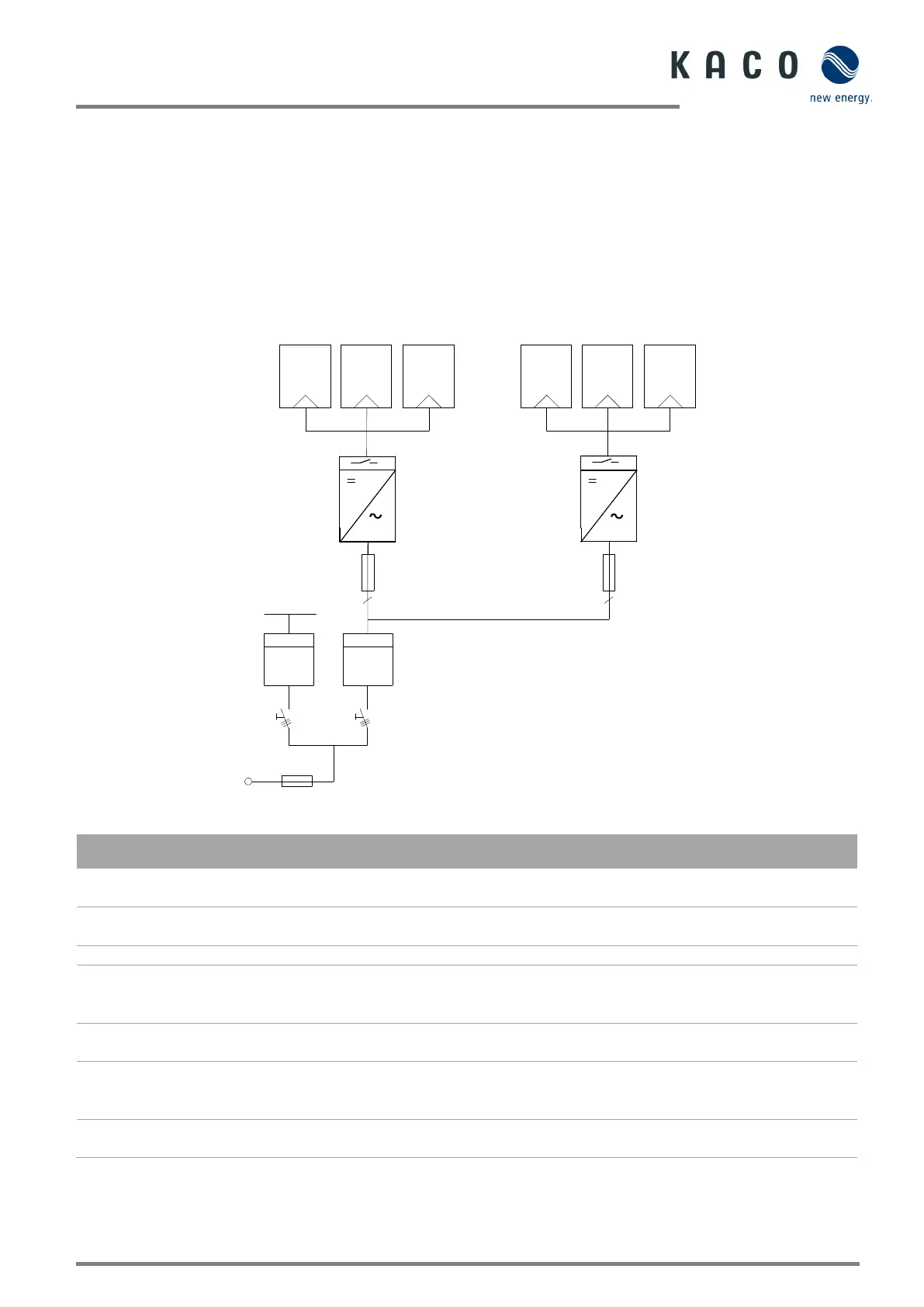
3.2 System layout
Fig. 2. Circuit diagram of a system with two inverters
Key Definition / information on the connection
The PV generator converts the radiant energy of sunlight
into electrical energy.
The PV generator is connected to the device’s DC
connection.
The circuit breaker is an overcurrent protection device.
The feed-in meter is to be specified and installed by the
power supply company. Some power supply companies
also allow the installation of your own calibrated counters.
The selective main switch is to be specified by the power
supply company.
The reference counter is to be specified and installed by
the power supply company. This measures the amount of
Integrated DC isolator switch
Use the integrated DC isolator switch to disconnect the
device from the PV generator.
Inverter Inverter
Load
Reference
counter
Grid monitoring point
Selective
main switch
PV generator PV generator
Feed-in meter
Line protection
Line protection
Selective
main switch

 Loading...