Tab. 1 Danger levels and their definition (personal injury) .................................................................... 1
Tab. 2 Danger levels and their definition (damage to property) ............................................................ 2
Tab. 3 Nameplate .................................................................................................................................. 4
Tab. 4 Options ....................................................................................................................................... 4
Tab. 5 Machine weight .......................................................................................................................... 5
Tab. 6 Temperature ............................................................................................................................... 5
Tab. 7 Ambient conditions ..................................................................................................................... 5
Tab. 8 Overview Ventilation ................................................................................................................... 6
Tab. 9 Safety relief valve activating pressure ........................................................................................ 6
Tab. 10 Free air delivery .......................................................................................................................... 7
Tab. 11 Cooling oil charge (Option K1) ................................................................................................... 8
Tab. 12 Cooling oil charge (Option W1) .................................................................................................. 8
Tab. 13 Compressor motor ...................................................................................................................... 9
Tab. 14 Compressor motor: Rated speed ............................................................................................... 9
Tab. 15 Noise emission ........................................................................................................................... 9
Tab. 16 Supply details 208V / 3ph / 60Hz ............................................................................................... 10
Tab. 17 Supply details 230V / 3ph / 60Hz ............................................................................................... 10
Tab. 18 Supply details 460V / 3ph / 60Hz ............................................................................................... 11
Tab. 19 Heat capacity (Option W1) ......................................................................................................... 11
Tab. 20 Danger Areas ............................................................................................................................. 18
Tab. 21 Safety signs ................................................................................................................................ 19
Tab. 22 Energy-saving control modes ..................................................................................................... 26
Tab. 23 Keys ........................................................................................................................................... 27
Tab. 24 Indicators .................................................................................................................................... 28
Tab. 25 RFID sensor field ........................................................................................................................ 29
Tab. 26 Voltage selection ........................................................................................................................ 38
Tab. 27 Overload protection cutout settings. ........................................................................................... 38
Tab. 28 Re-commissioning after storage ................................................................................................. 41
Tab. 29 Installation conditions checklist .................................................................................................. 41
Tab. 30 MODULATING control: Setting the shut-off valve ...................................................................... 43
Tab. 31 Machine identification ................................................................................................................. 49
Tab. 32 Remote control center identification ........................................................................................... 49
Tab. 33 Warning notice for timer control ................................................................................................. 50
Tab. 34 Other faults and actions ............................................................................................................. 52
Tab. 35 Warn others that the machine is being serviced. ....................................................................... 54
Tab. 36 Regular maintenance tasks ........................................................................................................ 56
Tab. 37 Oil change intervals lubricants ................................................................................................... 57
Tab. 38 Regular service tasks ................................................................................................................. 57
Tab. 39 Permissible cooling oil level under LOAD ................................................................................. 64
Tab. 40 Logged maintenance tasks ........................................................................................................ 76
Tab. 41 Consumable parts ...................................................................................................................... 77
List of Tables
9_5875 33 USE
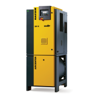
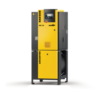
Operator Manual Screw Compressor
SM Tri-Voltage, SIGMA CONTROL 2
vii

 Loading...

