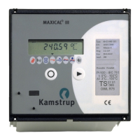
MAXICAL
®
III 5511-229 GB/98.06/Rev. B1
56
14.3 Inserting Analogue and Relay Module
An analogue and relay module (66-x0) can easily be fitted into an
existing MAXICAL
®
III. The module has 4 active analogue
outputs (4...20 mA) and two relay outputs for info code alarm and
limit switches respectively.
Order type no. 66-99-600 for a separate analogue and relay
module.
To fit the module, remove the back panel as described on the
previous page. Fit the module in the top section of the integrator,
so that the plug and socket mesh.
Use a stanley knife - or something similar - to cut the connection
holes free at terminal no. 80-93.
Replace the back panel and MAXICAL
®
III is ready for operation.
NB.:
Remember to reprogram MAXICAL
®
III subsequent to fitting a
new analogue and relay module, as the module is not programmed
on delivery. Use the programming software, 66-99-210.
MAXICAL
®
III must be supplied with 230 V AC during program-
ming.
14.4 Reseting MAXICAL
®
III
MAXICAL
®
III information codes can be reset via the optical read
out head or via data terminals 62-63-64. Data instruction “M3”
must be sent to the meter. The function is also available in the
programming software, 66-99-210. Select service and click on
reset infocode.
Furthermore, the information code can be reset by activating both
front plate buttons for approx. 10 s. until the display says ”Call”.
The hour counter can not be reset independently.
The meter can be totally reset by removing the back plate and
taking the main PCB out. Replace the PCB, simultaneously
pressing both keys on the front panel whilst you do so. This will
activate a total reset (energy, water, hour counter and info codes
will be cancelled).