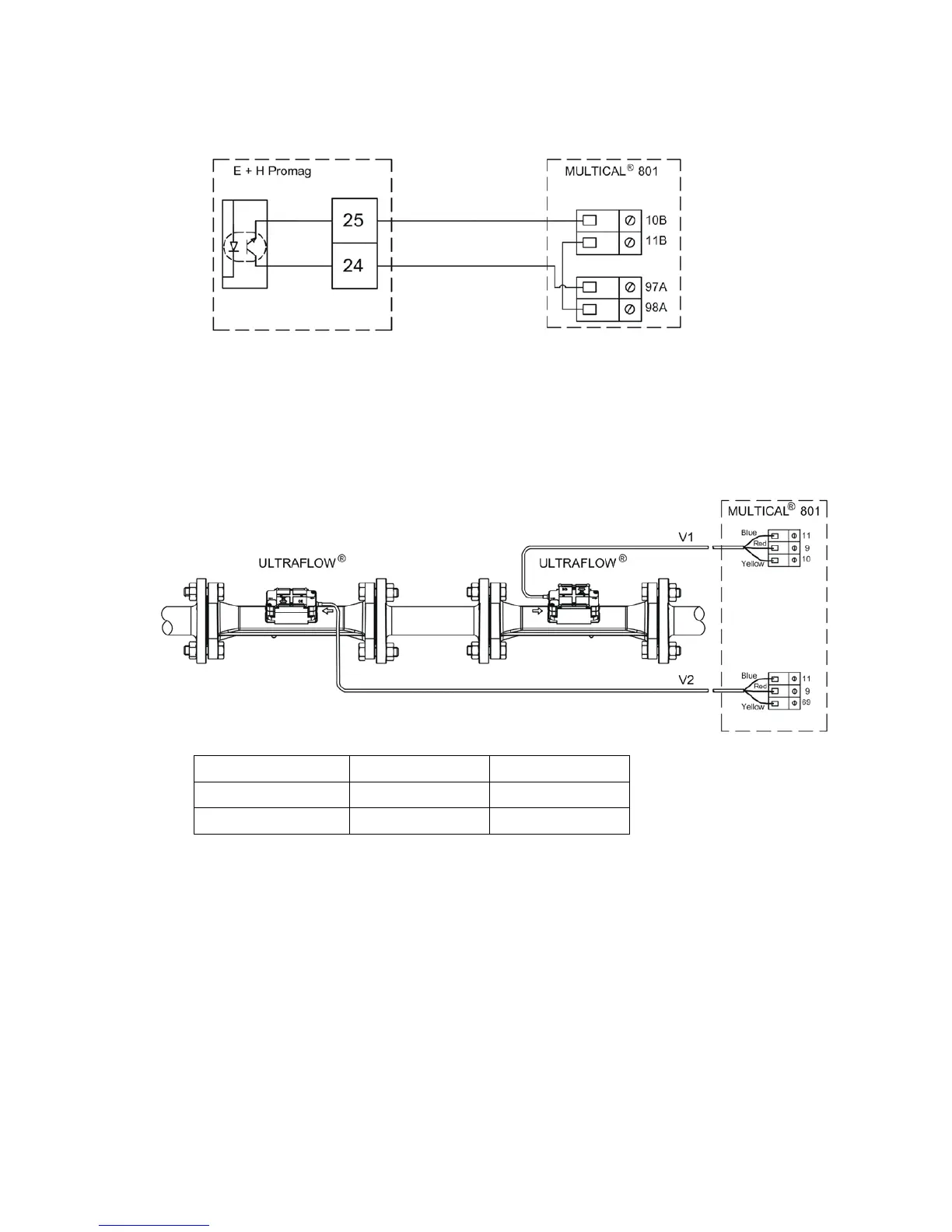
Figure 13
Auxiliary voltage from terminals 97A and 98A is added to the passive contact output on terminals 24 and 25
before the signal is connected to the galvanically separated flow sensor input. This permits a cable length of up to
100 m between flow sensor and calculator.
Heat energy Cooling energy
Same ΔΘ polarity E2 = V2 (T1-T2)k E1 = V1 (T1-T2)k
Changed ΔΘ polarity E2 = V2 (T1-T2)k E3 = V1 (T2-T1)k
Figure 14
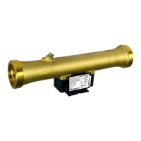
The two ULTRAFLOW
®
are installed ”back to back”, whereby one of the meters will measure flow, which one
depends on the flow direction.
ULTRAFLOW
®
is connected to the non-galvanically separated inputs. Up to 10 m cable length between flow
meter and calculator is thus possible.





 To Next Page