22
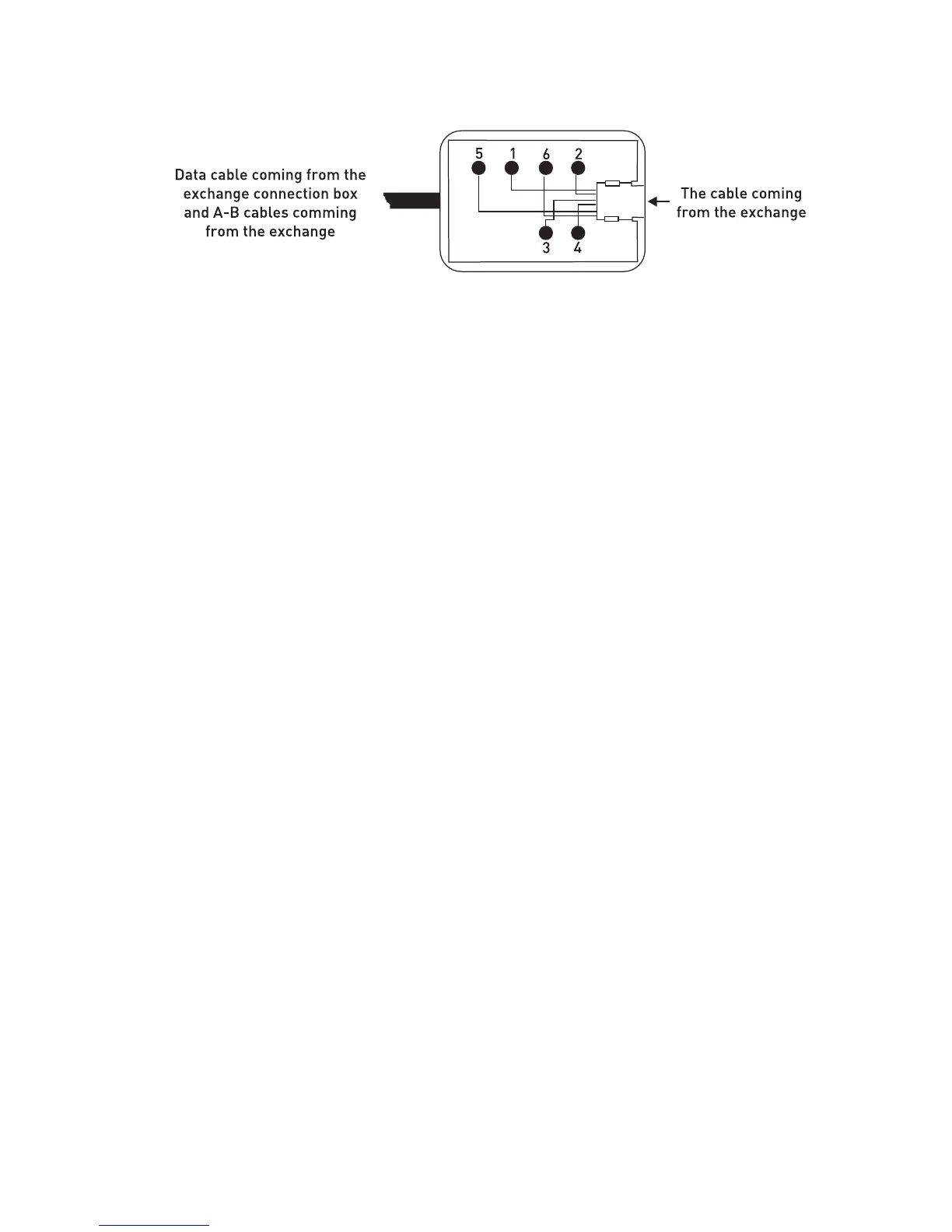
Those signals are present on the exchange connection box that is included in the
exchange hardware:
1. + 12 VDC
2. Busy
3. No connection
4. No connection
5. Ground (GND)
6. Data signal
NOTE: The “Busy” signal is used for KY16 Mini Printer, which is another KAREL
product.
If the distance between the exchange and FT10 is more than the total lengths of the
two cables mentioned above (approximately 4 meters), then it would be necessary to
obtain flat telephone cable in order to make the connection between the two connection
boxes. Note that the cable should comply with the standards.
Connecting FT10 To The Exchange:
Cabling of the first telephone to be connected to the KTS line of the
exchange:
1) Free end of the “system data cable” is attached to the KTS port socket of the system.
2) One end of the “telephone data cable” is attached to the connection box that is at the
end of the system data cable. The other end is connected to the FT10 telephone.
3) Connection of the A-B wires of the corresponding extension is made to the
connection box. In order to do that, two wires taken from the corresponding extension
connector of the exchange are attached to the red and green points on the connection
box.
NOTE1: If the exchange is MS26C, MS38S or MS224, and if the first FT10 will be
connected to the operator, then connections of the extension wires should not be
made, because the A and B connections for the operator are also ready on the KTS
sockets of those exchanges. Additional realization of those connections may prevent
the exchange from operating.