27
FT20 INSTALLATION
In order to operate the telephone, first, the spiral handset cable is connected to the
connection point under the telephone and to the handset. Then FT20 must be
connected to the KTS line of the exchange.
Required Hardware For The Connection:
FT20 is presented to the user together with a “telephone data cable” of length 2.5 m.
and a connection box. There are 6-pin, RJ-type male connectors at both ends of the
“telephone data cable”. One end of this cable has been attached to a 6-pin, RJ-type
female connector that is on the connection box. The connector at the other end of the
cable will be attached to its correspondent under FT20. The cavity, which is on the side
of the connection box without the 6-pin, RJ-type female connector, has been left for
other cabling that would be carried out on the box. (Parallel connection of the -48VDC /
/ GROUND (GND) + DATA signals and A / B terminal connections.)
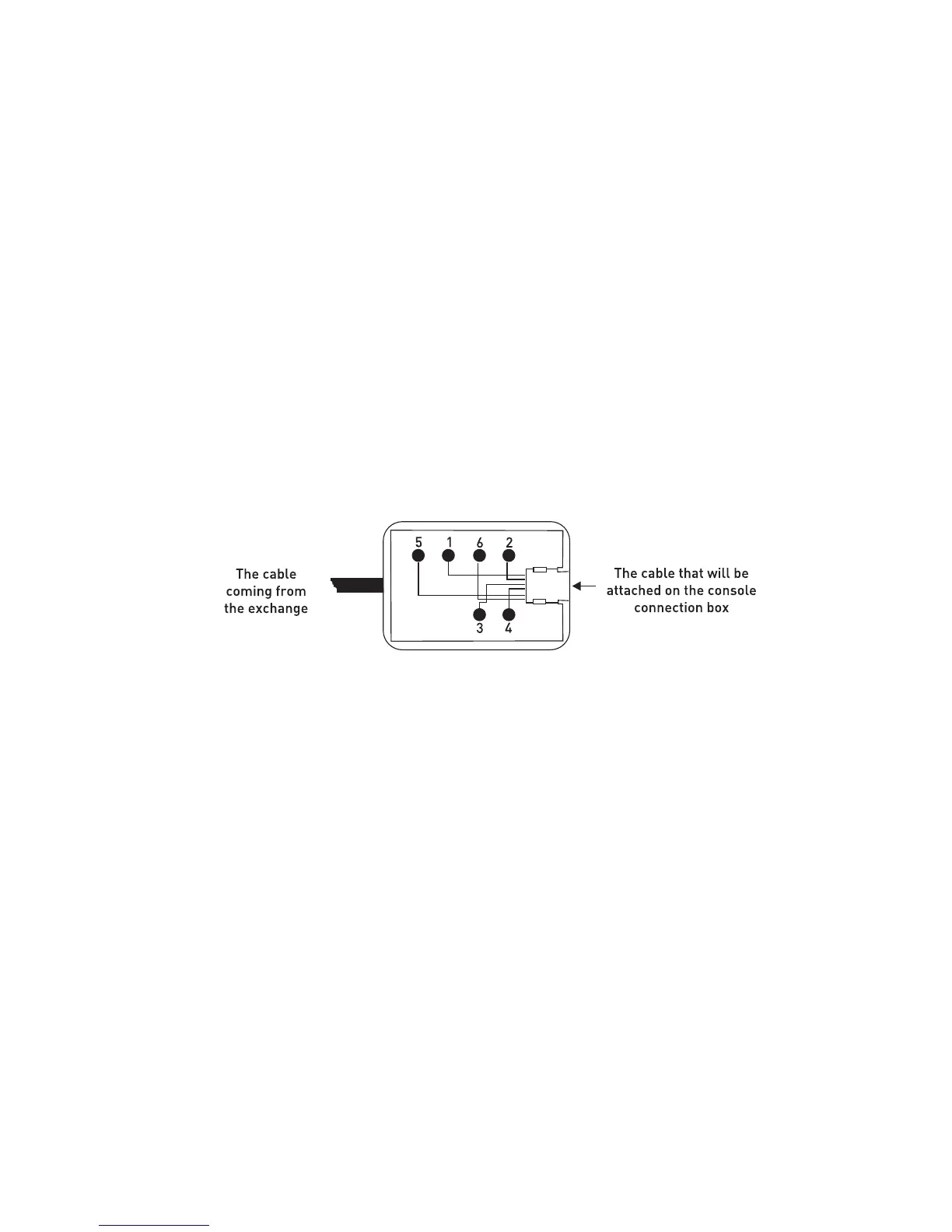
Those signals are present on the console connection box that is
included in the FT20 hardware:
1- - 48VDC
2- No connection
3- B (Tip) signal coming from
the corresponding extension
4- A (Ring) signal coming from
the corresponding extension
5- Ground (GND) + Data
6- No connection
In addition to the telephone data cable, another cable that can be used during
installation is the “system data cable”, which is distributed as one for each exchange.
One end of the “system data cable” has been attached to its connection box. On the
other, there is a connector at the free end of the cable, which is fit for the KTS (serial
data) port socket of the corresponding exchange.
The 6-pin, RJ-type male connector on the other side of the connection box will be
employed for parallel connection of -48 VDC / ground + data signals.