21
Brake Transistor Monitor
F Branch Circuit Fuses
CH Line Choke
EMI EMI Filter
BR Brake Resistor
LC Line Contactor
EC Elevator Control
VC Control Voltage
M Motor
RC Reset Contactor
Reset Reset Button
PT Power Terminal
++ for housings E,G,H
+PA for housings R,U,W
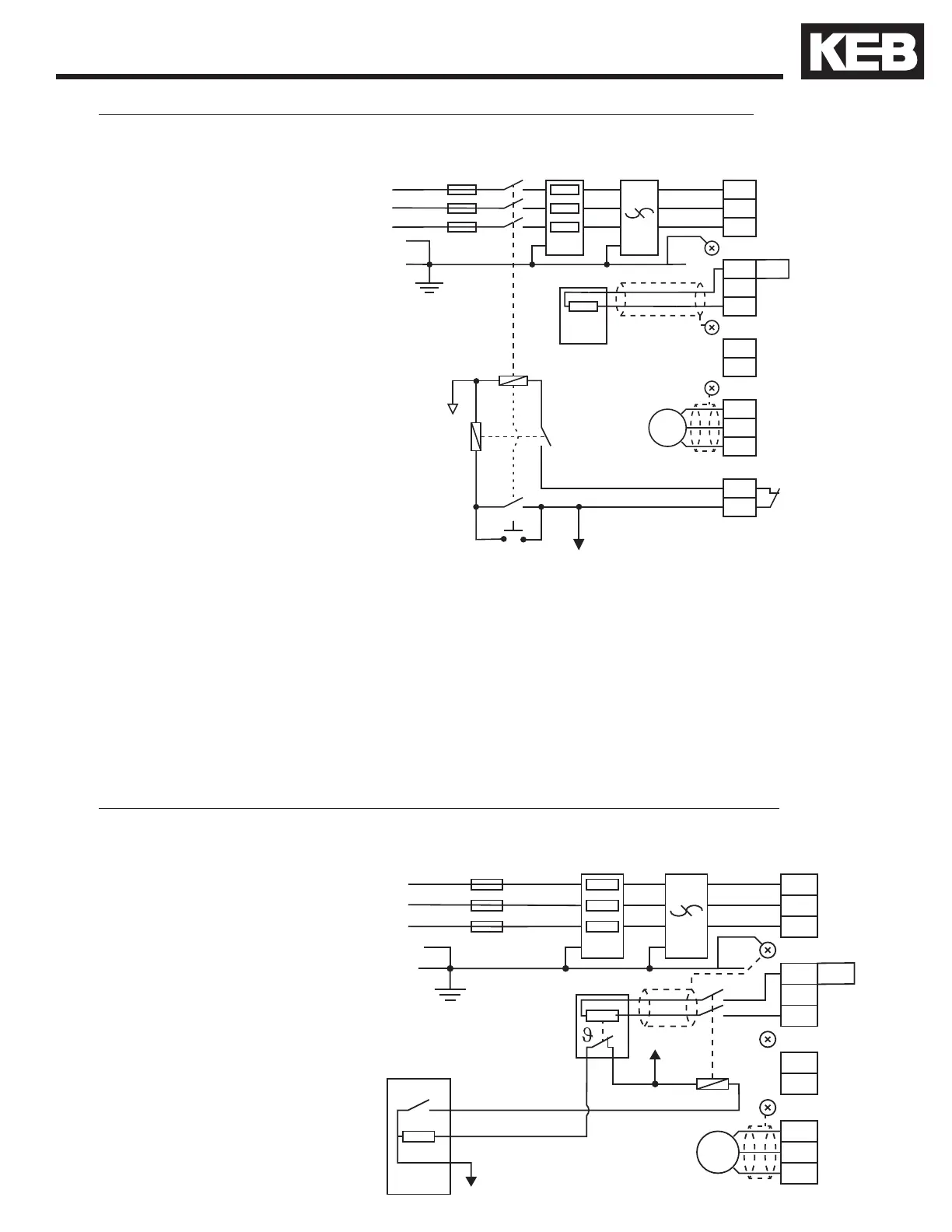
Brake Transistor Monitor without Elevator Controller Supervision: Line Contactor
Reset
VC
Com
F CH EMI
GND GND
L1
L2
L3
GND
GND
T1
T2
u
v
w
K1
K2
F5
X1A
GND
+ +
- -
PB
L1
L2
L3
BR
M
Brake Transistor
Watchdog
LC
GND
+PA PT
RC
F Branch Circuit Fuses
CH Line Choke
EMI EMI Filter
BR Brake Resistor
DC DC Contactor
EC Elevator Control
VC Control Voltage
M Motor
PT Power Terminal
++ for housings E,G,H
+PA for housings R,U,W
Temperature Sensor Monitor Circuit; Elevator Controller Supervision: DC Contactor
F CH EMI
GND GND
L1
L2
L3
GND
GND
T1
T2
u
v
w
F5
X1A
GND
+ +
- -
PB
L1
L2
L3
BR
DCEC
Out DC
In BRT
M
VC
Com
GND
PT+PA
For drives without the monitor circuit, a normally closed temperature
sensor on the brake resistor is wired either to the elevator controller or
to a contactor. If the temperature sensor indicates an over temperature
condition, either the elevator controller or the connected contactor must
remove the source of energy from the braking resistor. This can be done
either on the AC line side of the drive or the DC side with a resistor as
shown in the following wiring diagrams.
1.2.16. Temperature Sensor Wiring Diagrams

 Loading...


