44
Control Circuit - STO
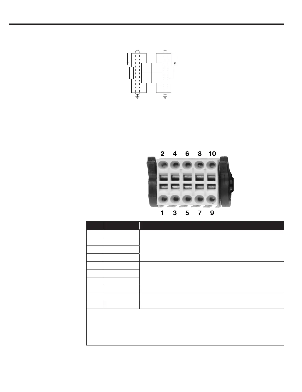
2.2.8. STO Connections (F5-K)
23
21
2224
Imax=10mA
0…10Vdc
I
max=10mA
0…10Vdc
X2B - Safety Control
2.2.7. Analog Outputs
(F5-K)
Pin Name Description
1 STO1+
Input STO Channel 1
2 STO1+
3 STO1-
4 STO1-
5 STO2+
Input STO Channel 2
6 STO2+
7 STO2-
8 STO2-
9 STO-OUT
Output STO
10 STO-OUT
The individual channels are designed potential-free, so 24V and 0V can
be connected. The inputs are designed by way that safety switchgear
units with test pulses (OSSD signals) can be connected. The signals are
not evaluated, they are only ltered. The OSSD test interval is limited to
10 ms.

 Loading...


