53
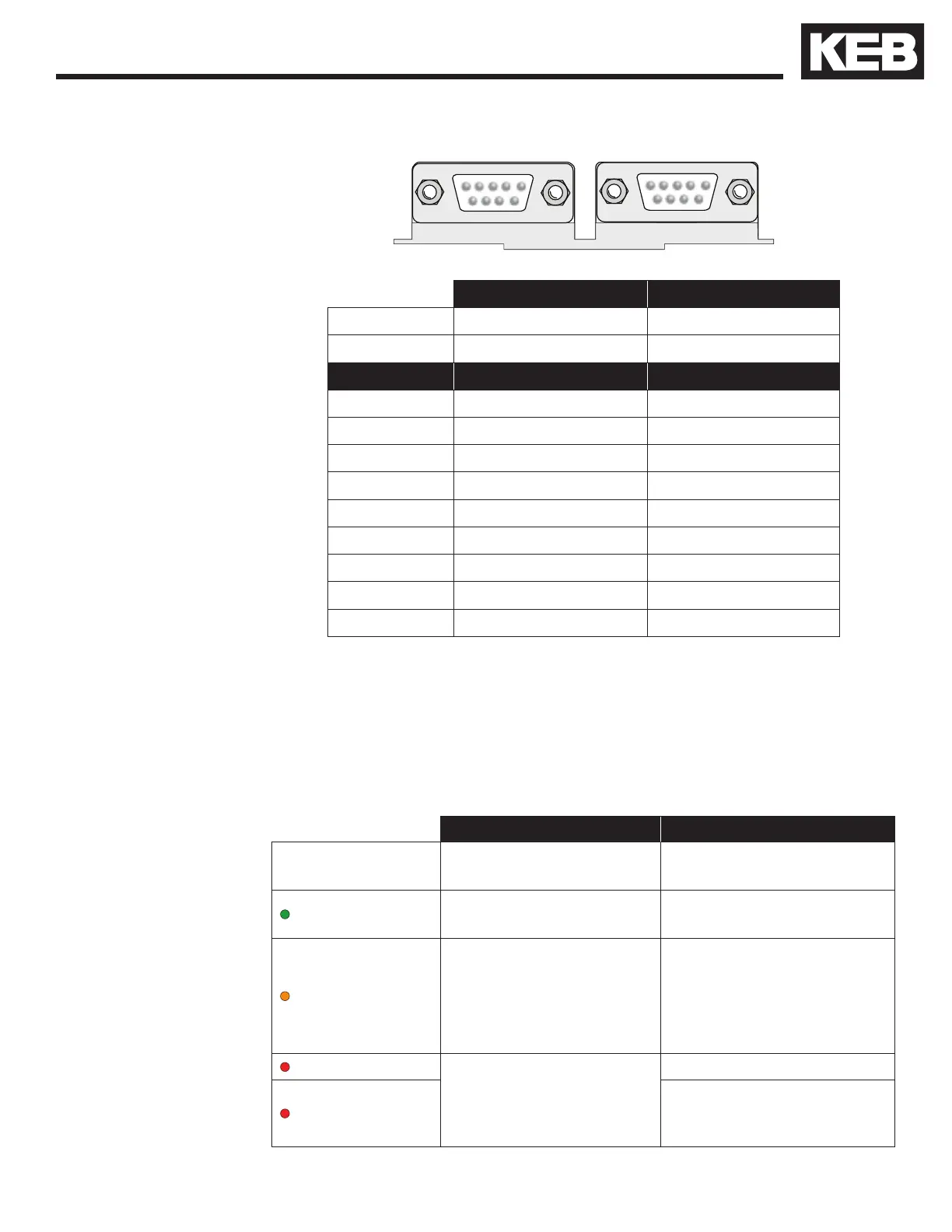
Serial/CAN Hardware Version
X6C X6D
X6C X6D
Hardware CAN | RS 485 RS 232/485
Use Bus Communications Diagnostics
Pin Signal Signal
1 CAN V+
2 CAN L TxD, RS232
3 CAN H RxD, RS232
4 RxD A -, RS485 RxD B +, RS485
5 RxD B +, RS485 RxD A -, RS485
6 CAN GND ) VP +5V (10mA)
7 Bus Ground Bus Ground
8 TxD A -, RS485 TxD B +, RS485
9 TxD B +, RS485 TxD A -, RS485
The LED indicators are available only on the Serial LCD Operator. The
LEDs are used to indicate operational status. They can be used for trou-
bleshooting and diagnostics. In addition, the function of the LED can be
changed with parameters CH10 - 15.
LED 1 LED 2
Off
No operation (noP)
Drive not enabled
(Green)
Inverter running the
motor
Run mode
Drive is able to run
(Orange)
-
Stop mode:
Drive is being
programmed or making
calculations;
FTP le transfer mode.
(Red - Blinking)
A limit has been
reached: Torque,
Current, or Voltage (not
yet implemented)
-
(Red - Solid)
Drive is faulted
3.2. Serial/CAN
Hardware Version
3.2.1. LED Indicators

 Loading...


