37
Control Connections
To prevent a malfunction caused by interference voltages on the control
inputs, the following steps should be observed:
• Establish a true earth ground for all ground connections!
• Do not connect drive signal commons to earth ground!
• Use shielded cable with twisted pair wires!
• Terminate shield wires to earth ground, only at inverter!
• Separate control and power wires by 8" or more!
• Control and power wires should cross at a right angle!
2.1.2. Connection of
the control signals
EMC
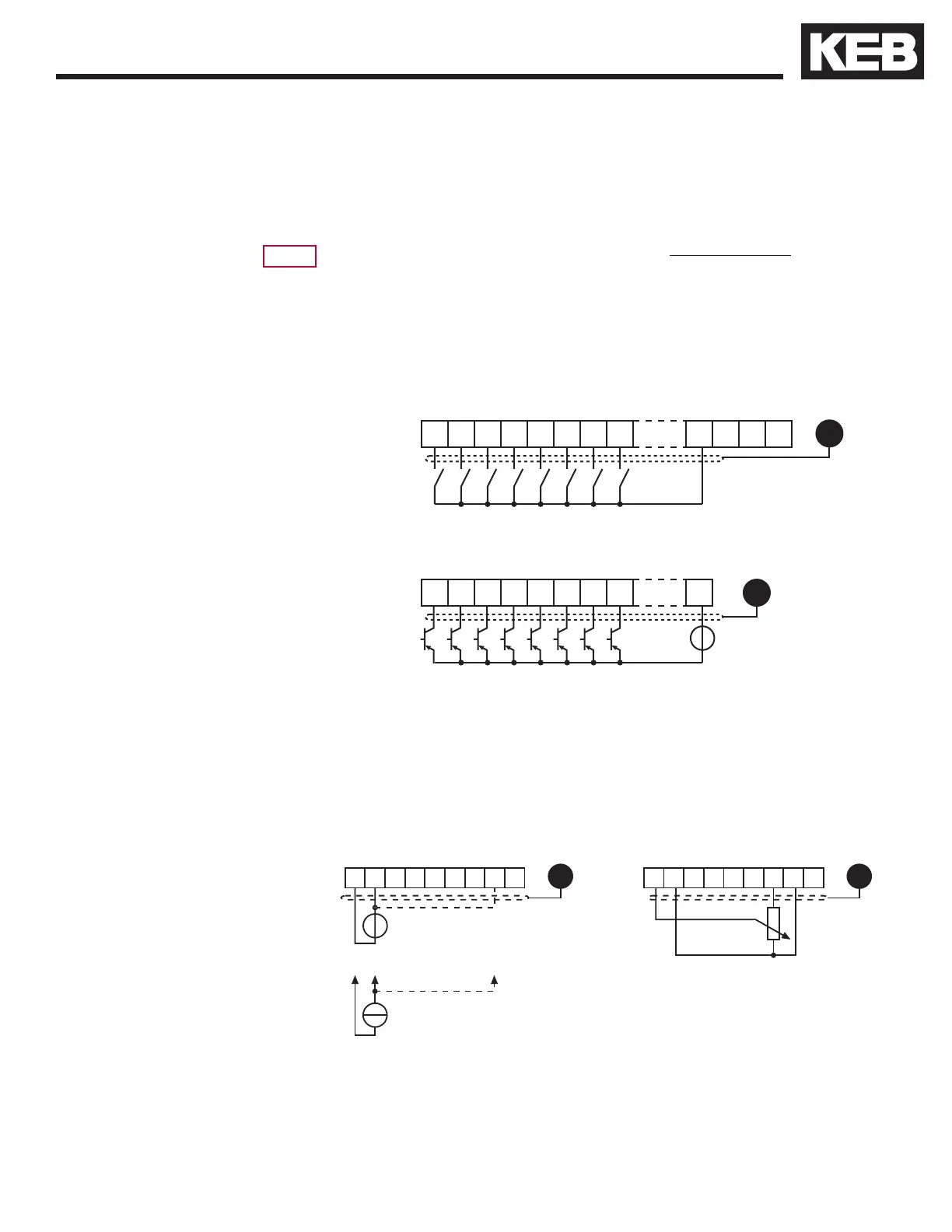
Connect unused analog inputs to common to eliminate noise signals!
X2A
123456789
GND
0...±10 VDC
Ri = 55 k
+
+
0(4)...20 mADC
Ri = 250
*
*
Use of external voltage supply
Ri = 2.1 kΩ
20...30 VDC
Regulated
Use of internal voltage supply
2.1.3. Digital Input
Speed Pattern, Torque Command2.1.4. Analog Inputs

 Loading...


