51
X3B Output TTL Incremental
The second incremental encoder connection serves as a buffered output of
the motor encoder. This can be used by other control systems for speed or
position control. The output signals are according to the RS422 line driver
signal standard.
2.2.5. X3B Output
TTL Incremental
Encoder Card Part Number: Housing Size ≤ E, 1MF5K81-DZ19. Housing
Size ≥ G 2MF5K81-DZ19.
The internal 24VDC power supply has a maximum load capacity of 170mA .
The 5V supply has a maximum load capacity of 500mA. Both of these val-
ues assume no loading on the supplies of connection X3A. If connections
or loads are placed on both terminals, the total load between the two must
not exceed these values.
ONLY when the inverter is switched off and the volt-
age supply is disconnected may the feedback con-
nectors be removed or connected!
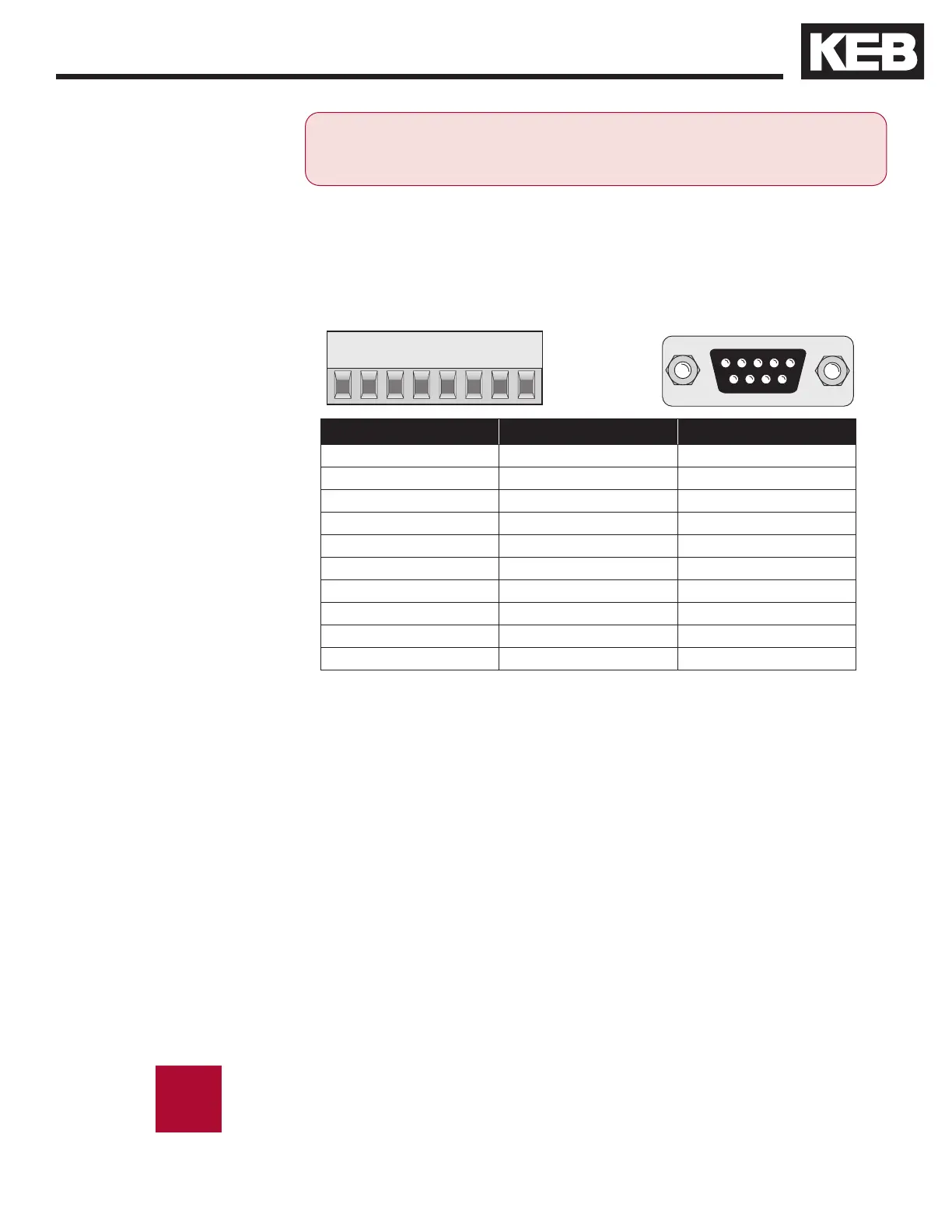
Plug in screw terminal
9 Pin Sub D - Female
The following specications apply to encoder interface X3B, channel 2
• Max. operating frequency: 200 kHz.
• External terminating resistance: R
t
= 120 Ohm
• RS422 level square wave
voltage level: 2...4 Vdc
For proper noise immunity, the RS422 standard requires a termina-
tion resistor be placed at the device which is receiving the simulated
encoder signal. The resistors shall be connected from A+ to A-, B+ to
B-, N+ to N- (only when used).
Pin No. (Terminal) Signal Pin No. (SubD)
1 A+ 1
3 B+ 2
5 N+ 3
7 +5.0V 4
- 24 ... 30V 5
2 A- 6
4 B- 7
6 N- 8
8 0V Com 9
Inverter Housing Earth GND Sub-D Housing

 Loading...


