27
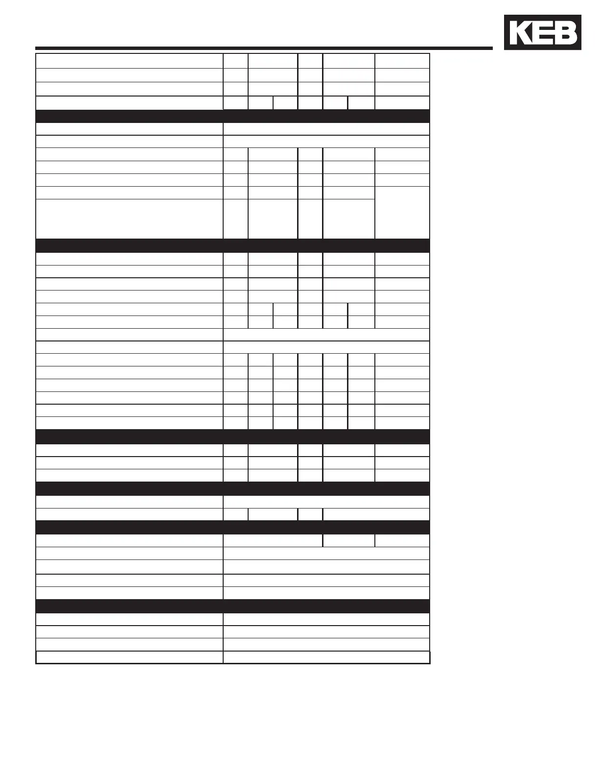
Technical data 480V (size 13 to 28)*
1) The 28 W housing can either be fed with one large set of wires or two smaller sets of wires, double feed. See Mat. No. 00F50EB-KW00 from KEB.
2) The wire gauge is based on the maximum fuse rating, copper wire with a 75°C insulation rating, THHW or equivalent. If circuit protection is selected based on the actual
input current, the wire size could be reduced.
3) This is the peak output current limited by hardware regulation. The software current control reserves 5% for closed loop regulation.
4) This is the maximum carrier frequency the power stage can support. The actual operating carrier frequency is adjusted and limited by the control card.
5) This is the power dissipation at the rated carrier frequency, rated voltage and rated load. Operation at reduced carrier frequencies or reduced load will decrease this value.
6) 12kHz
7) Max motor cable length when using shielded cable, KEB EMI lter, and the installation must conform to EN55011 / EN55022.
8) Min. resistance applies to 50% duty cycle.
Inverter Size
20 22 24 26 28
Max Motor Power [hp] 50 75 125 175 250
Housing Size H R U U W
Unit Hardware B B D B B D B
Input Ratings
Supply voltage [V] 305...528 ±0 (480 V Nominal voltage )
Supply voltage frequency [Hz] 50 / 60 +/- 2
Input phases
3 3 3 3 3 or 2x3
1)
Rated input current 400VAC [A] 83 127 198 275 385
(UL) Rated input current 480VAC [A] 72 105 172 231 362
UL minimum wire gauge
2)
[awg] 12 6 2 2
16mm stud
terminals. Use
UL approved
ring crimp
connectorUL maximum wire gauge
2)
[awg] 0 1/0 4/0 300 kcmill
Output Ratings
Rated output power [kVA] 52 80 125 173 256
Rated motor power [kW] 37 55 90 132 200
Rated output current 400VAC [A] 75 115 180 250 370
(UL) Rated output current 480VAC [A] 65 96 172 231 332
Peak current (30 seconds)
3)
[A] 135 172 230 270 375 450 74 0
Over current fault (E.OC) trip level [A] 162 207 276 324 450 540 888
Output voltage [V] 3 x 0…Vsupply
Output frequency [Hz] Generally 0 to 599Hz (limited by control board and carrier frequency)
Rated switching frequency
4)
[kHz] 4 8 8 8 4 4 2
Maximum switching frequency [kHz] 16 16 16 8 8 12 8
Power loss at rated operation
5)
[W] 900 1500 1500 2400 2800 2800 3500
Stall current at 4kHz [A] 83 115 173 198 330 330 574
Stall current at 8kHz [A] 83 115 150 180 180 225 407
Stall current at 16kHz [A] 45 63 98 – – 125
6)
–
Braking Circuit
Min. braking resistance [Ohm] 9 7. 5 4 2.2
8)
1. 2
Typ. braking resistance [Ohm] 13 9 6 4.3 2.3
Max. braking current [A] 90 104 200 364 660
Installation Information
Max. shielded motor cable length
7)
[ft] 165
Tightening torque for power terminals [in lb] 35 53 133 220
Environmental
Max. heat sink temperature TOH [°C] 90°C / 194°F 60°C / 140 °F 90°C / 194 °F
Storage temperature [°C] -25...70 °C / -13…158°F
Operating temperature
[°C]
-10...45 °C / 14…113°F
Housing design / protection Chassis / IP20 / Pollution Degree 2
Relative humidity max. 95% without condensation
Approvals
Tested in accordance with… EN 61800-3 /UL508C
Standards for emitted interference EN 55011 Class B / EN 55022 Class A
Standards for noise immunity IEC 1000-4-2 / -3 / -4 / -5/ -6
Climatic category 3K3 in accordance with EN 50178

 Loading...


