47
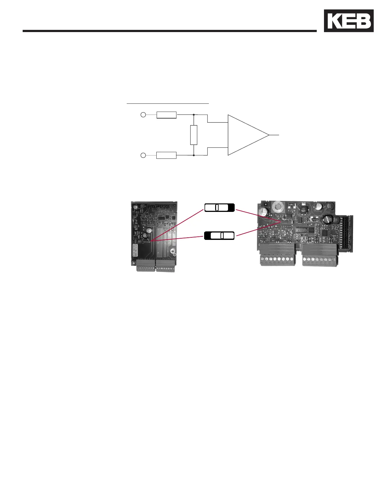
Input equivalent circuit
The following specications apply to encoder interface X3A, channel 1
• Max. operating frequency: 300 kHz.
• Internal terminating resistance: R
t
= 120 Ω
• RS422 or TTL level square wave
voltage level: 2...5 Vdc
A +
B +
A -
B -
approx.
120 Ω
approx.
34 Ω
Selection of the supply voltage
The maximum load capacity is dependent on the selected voltage supply.
• Max. load capacity with 15V internal supply:300 mA
• Max. load capacity with 24 V internal supply:170 mA
• Max. load capacity with an external 24V supply 1 A (dependent on the
external voltage source)
The specied currents are reduced by any current drawn on the second
interface X3B (see Section 3.3.9).
For maximum noise immunity, the encoder cable shall consist of individually
shielded twisted pairs with one overall shield. The individual shields should be
connected to 0V (com) pin 8 on the X3A terminal strip and be kept electrically
isolated from the outer shield. The outer shield should be connected to earth
ground on the elevator drive.
The cable shall be kept a minimum of 8 inches (20 cm) away from all wires
having greater than 24VDC on them. For best results run the encoder
cable in a separate conduit from the controller to the motor.
15 V
24 V or external sup-
ply via the control
card

 Loading...


