Key matrix
The front panel keys (S401-S430) are organized into a row-column matrix to minimize the
number of microcontroller peripheral lines required to read the keyboard. A key is read by strob-
ing the columns and reading all rows for each strobed column. Key down data is interpreted by
the display microcontroller and sent back to the main microprocessor using proprietary encod-
ing schemes.
Power supply
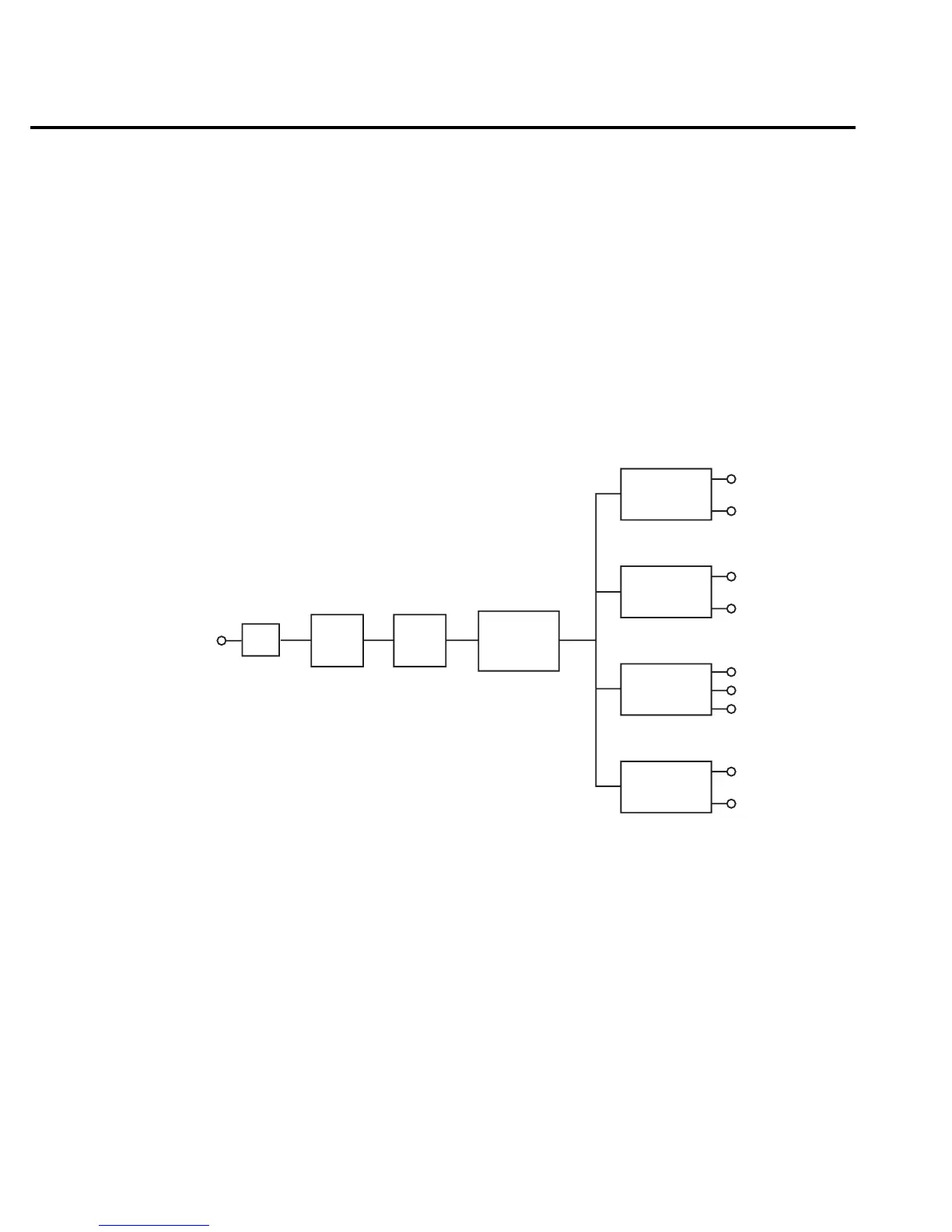
The following information provides some basic circuit theory that can be used as an aid to
troubleshoot the power supply. A block diagram of the power supply is shown in Figure 2-1.
AC power is applied to the AC power module receptacle (J1009). Power is routed through the
line fuse and line voltage selection switch of the power module to the power transformer. The
power transformer has a total of four secondary windings for the various supplies.
AC voltage for the display filaments is taken from a power transformer secondary at F1 and
F2, and then routed to the display board.
Each DC supply uses a bridge rectifier, a capacitive filter arrangement and a regulator. Table
2-1 summarizes rectifier, filter and regulator circuits for the various supplies.
Figure 2-1
Power supply
block diagram
Fuse
Power
Switch
Line
Voltage
Switch
Power
Transformer
CR104
C128, C156
U144
+5VD
D Common
CR116, CR117
C104, C108
U101
CR102
C131, C148
U119, U125
CR103
C146
U124
+37V
D Common
+15V
A Common
-15V
+5V, +5VRL
A Common
2-6 Troubleshooting