1
Routine Maintenance
1-1
1.1 Introduction
In general, the information in this section deals with
routine type maintenance that can be performed by the
operator. This information is arranged as follows:
1.2 Line fuse replacement
Explains how to re-
place a blown line power fuse.
1.3 Current fuse replacement
Explains how to re-
place a blown current fuse.
1.4 Fan Þlter cleaning
Explains how to remove
and clean the Þlter element for the cooling fan.
1.5 Firmware updates
Recommends a course of
action for Þrmware updates provided by Kei-
thley.
1.2 Line fuse replacement
WARNING
Disconnect the line cord at the rear
panel. Remove all test leads connect-
ed to the instrument (front and rear).
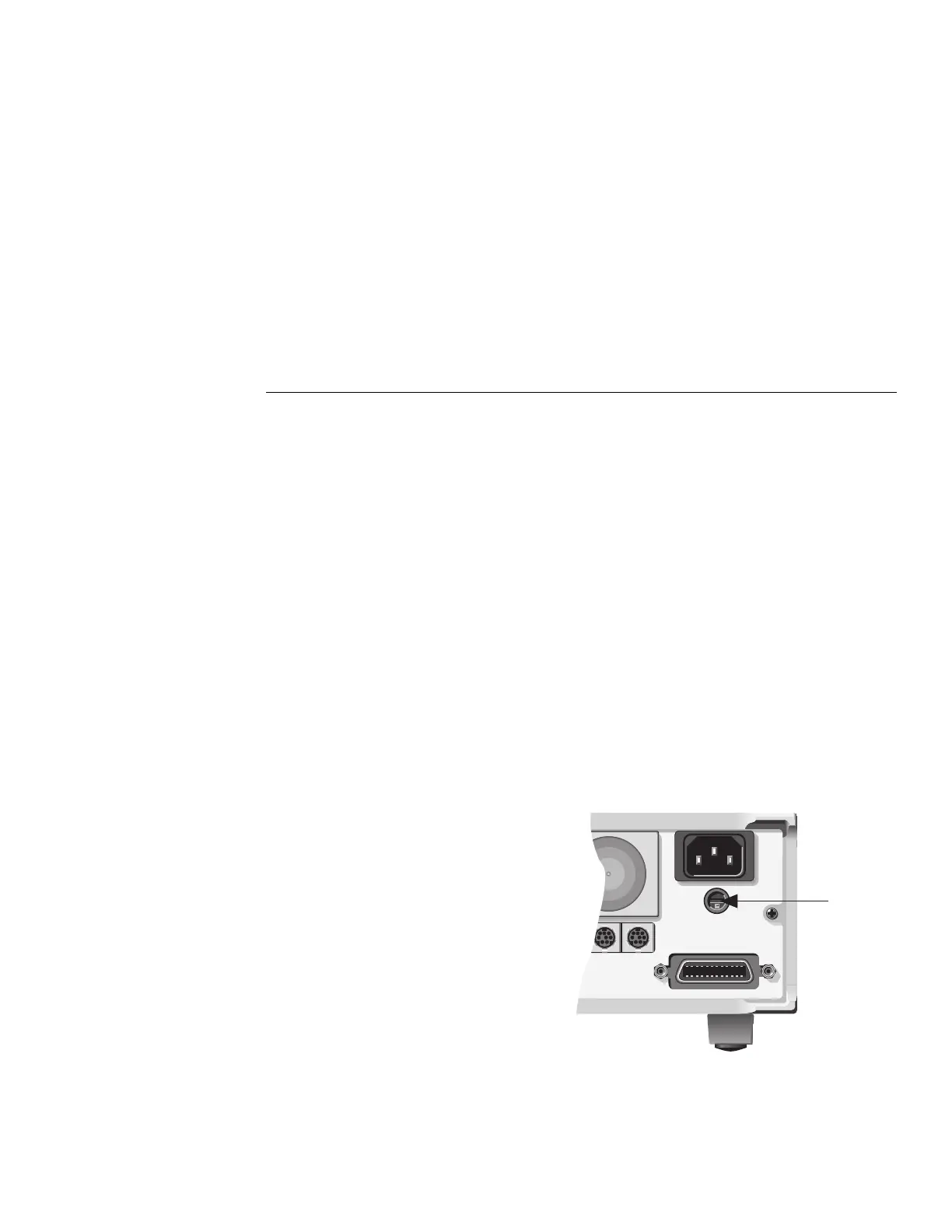
The power line fuse is accessible from the rear panel,
just below the ac power receptacle (see Figure 1-1). Per-
form the following steps to replace the line fuse:
1. Insert a bladed screwdriver into the slot of the fuse
carrier.
2. While pushing in, turn the screwdriver counter-
clockwise until the spring loaded fuse carrier re-
leases from the fuse holder.
3. Pull out the fuse carrier and replace the fuse with
the type speciÞed in Table 1-1.
CAUTION
To prevent instrument damage, use
only the fuse type speciÞed in Table
1-1.
4. Re-install the fuse carrier.
Figure 1-1
Line fuse location
OR SERVICABLE PARTS,SERVICE BY QUALIFIED PERSONNEL ONLY.
OR SERVICABLE PARTS,SERVICE BY QUALIFIED PERSONNEL ONLY.
N AGAINST FIRE HAZARD,REPLACE FUSE WITH SAME TYPE AND RATING.
AGAINST FIRE HAZARD,REPLACE FUSE WITH SAME TYPE AND RATING.
DIGITAL I/O
TRIGGER
LINK
IN OUT
LINE RATING
90-134VAC
180-250VAC
50, 60, 400HZ
55VA MAX
LINE FUSE
SLOWBLOW
1/2A, 250V
IEEE-488
(CHANGE IEEE ADDRESS
WITH FRONT PANEL MENU)
Line
Fuse