Troubleshooting
2-3
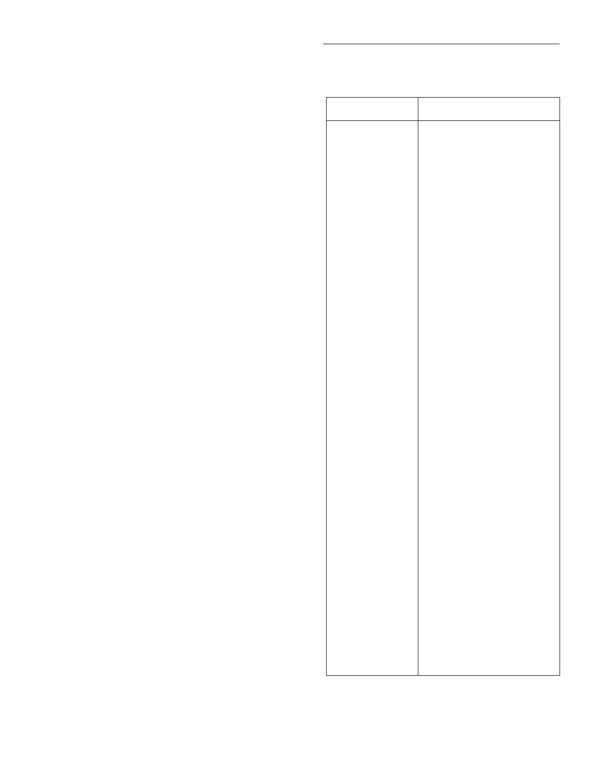
Table 2-1
Built-in-test summary
Test Circuit tested/exercised
100 Series
100.1
Memory:
EPROM
101 Series
101.1
Memory:
RAM
102 Series
102.1
Memory:
E
2
PROM
103 Series
103.1 - 103.4
103.5
Digital I/O:
Digital Output
Digital Input
104 Series
104.1
104.2
IEEE-488 Bus:
Handshake
Data
105 Series
105.1 - 105.6
105.7
105.8
105.11 - 105.18
Triggers:
System Trigger Bus
External Trigger /Voltme-
ter Complete
Group Execute Trigger
(GET)
Trigger Shorts
200 Series
200.1
200.2
200.3
200.4
200.5
200.6
200.7
A/D Converter:
A/D Zero
A/D Noise
FAST Circuit
x10 Line Cycle Integration
x0.1 Line Cycle Integration
x0.02 Line Cycle Integra-
tion
x0.01 Line Cycle Integra-
tion
201 Series
201.1
201.2
201.3
Calibration:
Test Cal Zero
7V Reference
1.75V Reference
300 Series
300.1
300.2
300.3
A/D Multiplexer (MUX),
A/D Buffer:
7V Reference, x1.5 Gain
1.75V Reference, x5 Gain
0V Reference, x50 Gain
301 Series
301.1
301.2
Input Buffer:
Front End (FE) Zero
Divide by 100
FRONT PANEL TESTS
KEYS DISPLAY-PATTERNS
4. Place the cursor on DISPLAY-PATTERNS and
press ENTER to start the display test. There are Þve
parts to the display test. Each time a front panel
key (except EXIT) is pressed, the next part of the
test sequence is selected. The Þve parts of the test
sequence are as follows:
A. Checkerboard pattern (alternate pixels on) and
all annunciators.
B. Checkerboard pattern and the annunciators
that are on during normal operation.
C. Horizontal lines (pixels) of the Þrst digit are se-
quenced.
D. Vertical lines (pixels) of the Þrst digit are se-
quenced.
E. Each digit (and adjacent annunciator) is se-
quenced. All the pixels of the selected digit are
on.
5. When Þnished, abort the display test by pressing
EXIT. The instrument returns to the SELF-TEST
MENU. Keep pressing EXIT to back out of the
menu structure.
2.5 Built-in test
BUILT-IN TEST is used to test and exercise various cir-
cuits and components on the digital board, analog
board and A/D converter board. The Built-In Tests are
listed in Table 2-1. Many of the tests are actual pass/fail
type tests, while others are circuit exercises that are
used for subsequent tests. Each Built-In Test can be run
manually. After a test is manually run, operation is
ÒfrozenÓ to allow the technician to troubleshoot the cir-
cuit. Troubleshooting documentation for each Built-In
Test is provided in paragraph 2.10.3.
 Loading...


