Routine Maintenance
1-2
NOTE
If the power line fuse continues to
blow, a circuit malfunction exists and
must be corrected. Refer to the trou-
bleshooting section of this manual for
assistance.
1.3 Current fuse replacement
Each AMPS input (front and rear) has its own current
fuse. When replacing a current fuse, use the type spec-
iÞed in Table 1-2.
WARNING
Disconnect the instrument from the
power line and remove all test leads
(front and rear).
1.3.1 Front AMPS input fuse
The front panel AMPS jack functions as the AMPS in-
put terminal and as the carrier for the AMPS fuse (see
Figure 1-2). Perform the following steps to replace the
fuse:
1. Push in the AMPS input jack and turn counter-
clockwise until the spring loaded fuse carrier re-
leases from the fuse holder.
2. Pull out the fuse carrier and replace the fuse with
the type speciÞed in Table 1-2.
CAUTION
To prevent instrument damage, use
only the type speciÞed in Table 1-2.
3. Re-install the fuse carrier.
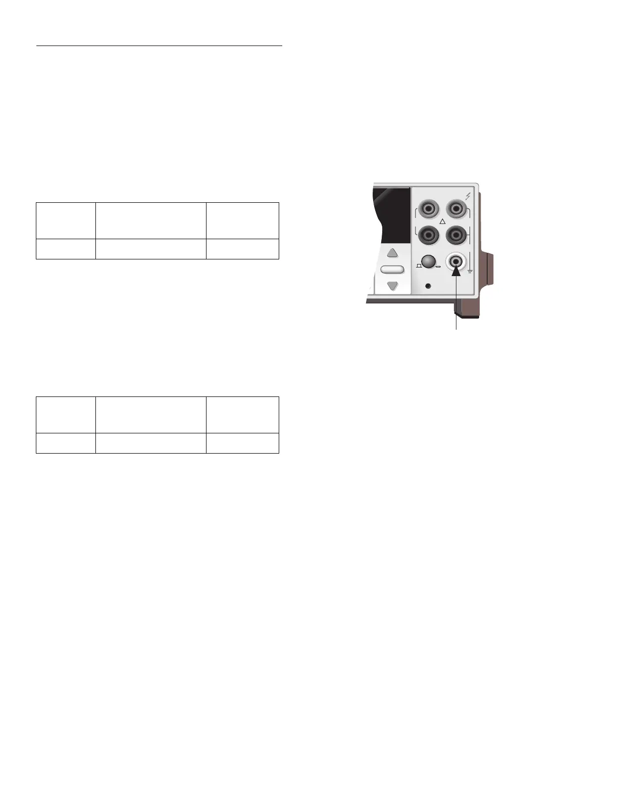
1.3.2 Rear AMPS input fuse
The rear AMPS input fuse is located just below the
AMPS input jack (see Figure 1-3). Perform the follow-
ing steps to replace the fuse:
1. Insert a bladed screwdriver into the slot of the fuse
carrier.
2. While pushing in, turn the screwdriver counter-
clockwise until the spring loaded fuse carrier re-
leases from the fuse holder.
3. Pull out the fuse carrier and replace the fuse with
the type speciÞed in Table 1-2.
CAUTION
To prevent instrument damage, use
only the fuse type speciÞed in Table
1-2.
4. Re-install the fuse carrier.
Table 1-1
Power line fuse
Size Rating
Keithley
Part No.
5
×
20mm 250V,
½
A, Slo-Blo FU-71
Table 1-2
Current fuse
Size Rating
Keithley
Part No.
5
×
20mm 250V, 2A, Normal-Blo FU-48
Figure 1-2
Front AMPS input fuse location
2001 MULTIMETER
RANGE
RANGE
MATH 4W AUTO ARM TRIG SMPL
!
FR
500V
PEAK
FRONT/REAR
2A 250V
AMPS
CAL
HI
INPUT
LO
SENSE
Ω 4 WIRE
INPUTS
350V
PEAK
1100V
PEAK
AUTO
AMPS
Fuse