Troubleshooting
2-113
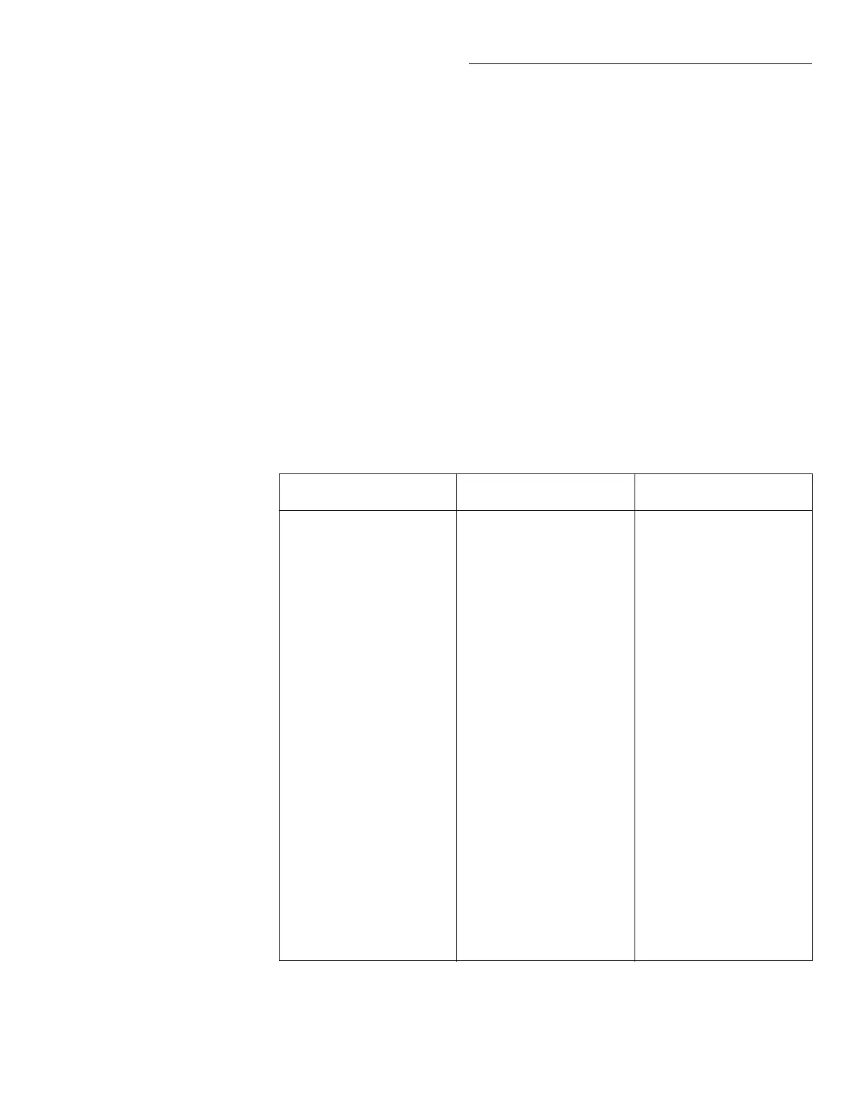
Test 411.1 – Filter; true RMS
Pass/Fail
Cannot measure 7V ±0.18V at A/D IN.
VRIN is buffered by U517 and tied to BUFF. The signal at BUFF is routed through R233,
K503, K500, the input protection circuit and Q513 to the input buffer (Q512 and U520).
The buffered signal is tied to AMP IN.
The signal at AMP IN is then routed to the variable gain ampliÞer (VGA) and, being
positive, follows the non-inverting x1 path that consists of R530, Q509, Q507, U519,
R531, U509, Q501, and U516 to pin 15 of the TRMS converter U517.
The output of the U517 is routed through analog switch U510 to the Þlter that consists
of components R220, R221, R222, C581, C582, C583, and U523. The output of the Þlter
is connected to the multiplexer (U511) at pin 5. The output (OUT) of the multiplexer is
routed through buffer U342 to ACV/A. The signal at ACV/A is routed through U320
(/AC pulled low) and applied to the A/D buffer (U322), which is conÞgured for x1
gain. Measure the output at A/D IN.
DC_STB
Registers
R1_STB
Registers
R2_STB
Registers
U801 Q1: 0
Q2: 1
Q3: 1
Q4: 1
Q5: 1
Q6: 0
Q7: 0
Q8: 0
U307 Q1: 1
Q2: 1
Q3: 0
Q4: 1
Q5: 1
Q6: 1
Q7: 1
Q8: 1
U505 Q1: 0
Q2: 1
Q3: 1
Q4: 1
Q5: 0
Q6: 1
Q7: 0
Q8: 1
U800 Q1: 1
Q2: 1
Q3: 0
Q4: 0
Q5: 0
Q6: 0
Q7: 1
Q8: 1
U305 Q1: 1
Q2: 0
Q3: 1
Q4: 0
Q5: 0
Q6: 0
Q7: 1
Q8: 1
U500 Q1: 1
Q2: 0
Q3: 0
Q4: 1
Q5: 1
Q6: 1
Q7: 0
Q8: 1
U300 Q1: 1
Q2: 1
Q3: 1
Q4: 1
Q5: 1
Q6: 1
Q7: 1
Q8: 1
U302 Q1: 1
Q2: 1
Q3: 1
Q4: 1
Q5: 1
Q6: 1
Q7: 1
Q8: 0
U530 Q1: 0
Q2: 0
Q3: 0
Q4: 0
Q5: 0
Q6: 0
Q7: 1
Q8: 1
U303 Q1: 0
Q2: 1
Q3: 1
Q4: 1
Q5: 0
Q6: 1
Q7: X
Q8: X
U501 Q1: 1
Q2: 0
Q3: 0
Q4: 1
Q5: 1
Q6: 0
Q7: X
Q8: X
Note: Tables 2-10 through 2-12 provide functional descriptions of the register bits.
Type
Failure analysis
Description
Bit pattern

 Loading...


