Troubleshooting
2-37
Test 201.3 – 1.75V reference
Pass/Fail
Cannot measure 1.75V at A/D IN.
This test turns on Q328 by setting /HIV low and turns on Q525 by setting /DIVIDER
low. Two switches of U318 (/2VREF pulled low) and (/X1 pulled low) are closed and
U808 is set to line cycle integration.
The 1.75V reference is connected to the A/D buffer at x1 gain and 1.75V REF is applied
to the A/D converter. The A/D is triggered and the 1.75V REF counts are stored. A cal-
culation is performed using the values stored in tests 200.1, 200.2, and 200.3.
U327, U330, U329, U328 and associated resistors and capacitors.
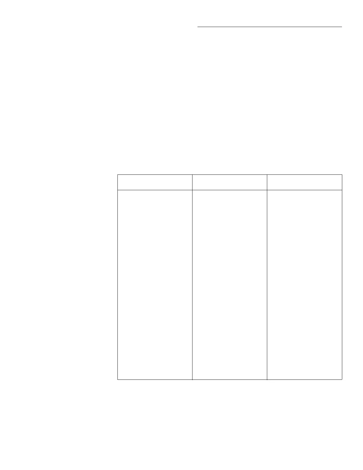
DC_STB
Registers
R1_STB
Registers
R2_STB
Registers
U801 Q1: 0
Q2: 1
Q3: 1
Q4: 1
Q5: 1
Q6: 0
Q7: 0
Q8: 0
U307 Q1: 1
Q2: 1
Q3: 0
Q4: 1
Q5: 1
Q6: 1
Q7: 1
Q8: 1
U505 Q1: 0
Q2: 0
Q3: 1
Q4: 0
Q5: 0
Q6: 0
Q7: 0
Q8: 0
U800 Q1: 1
Q2: 1
Q3: 0
Q4: 0
Q5: 0
Q6: 0
Q7: 1
Q8: 1
U305 Q1: 1
Q2: 0
Q3: 1
Q4: 0
Q5: 0
Q6: 0
Q7: 1
Q8: 1
U500 Q1: 1
Q2: 1
Q3: 0
Q4: 1
Q5: 1
Q6: 1
Q7: 1
Q8: 1
U300 Q1: 1
Q2: 1
Q3: 1
Q4: 1
Q5: 1
Q6: 1
Q7: 1
Q8: 0
U302 Q1: 1
Q2: 1
Q3: 1
Q4: 1
Q5: 1
Q6: 1
Q7: 1
Q8: 0
U530 Q1: 0
Q2: 0
Q3: 0
Q4: 0
Q5: 0
Q6: 0
Q7: 0
Q8: 1
U303 Q1: 0
Q2: 1
Q3: 1
Q4: 0
Q5: 1
Q6: 1
Q7: X
Q8: X
U501 Q1: 1
Q2: 1
Q3: 0
Q4: 1
Q5: 1
Q6: 1
Q7: X
Q8: X
Note: Tables 2-10 through 2-12 provide functional descriptions of the register bits.


 To Next Page