8: Grading and binning resistors Model DMM7510 7½ Digit Multimeter
8-2 DMM7510-900-01 Rev. B / May 2015
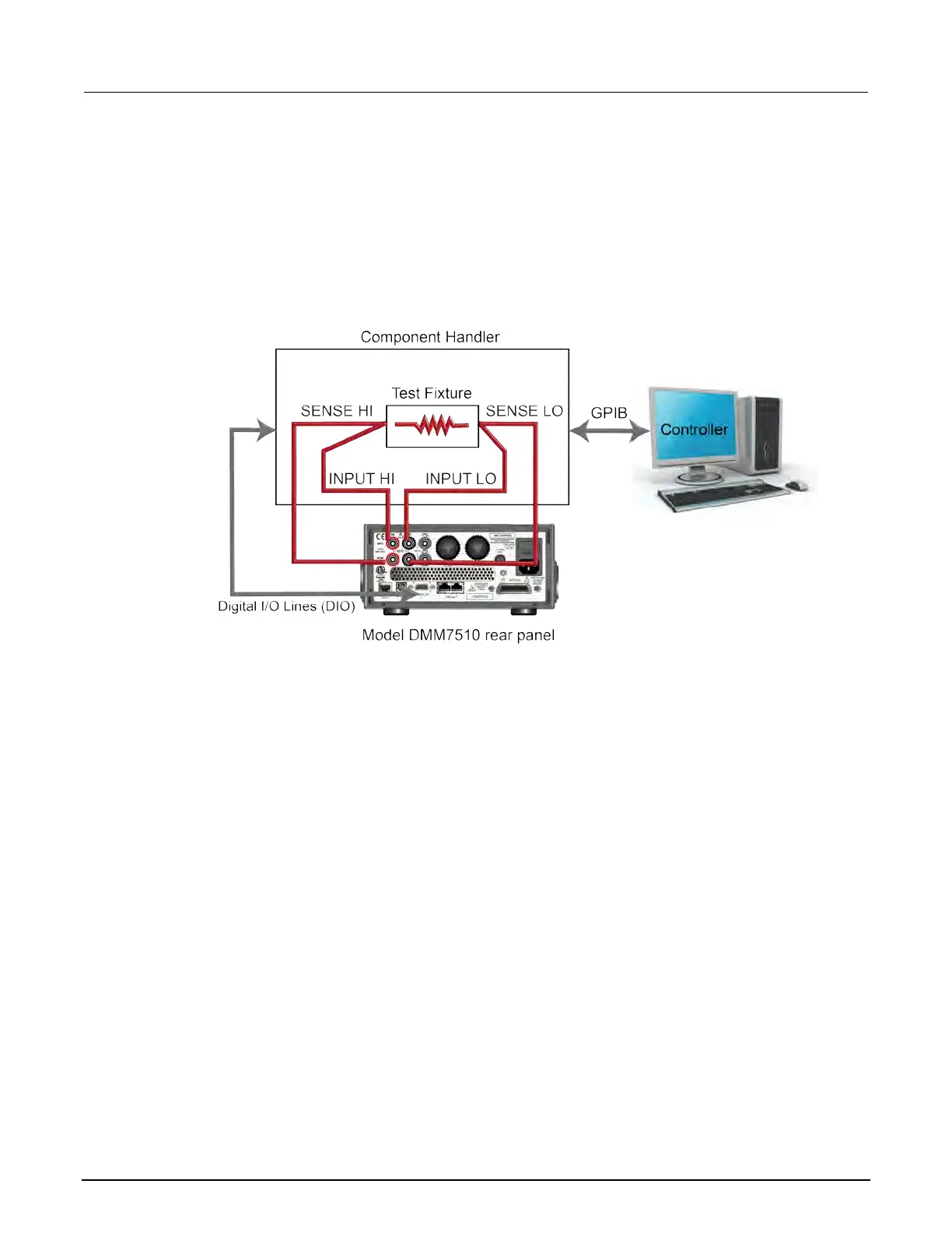
Instrument connections
In this example, the output signals that represent the grading results are sent from the Model
DMM7510. The signals are sent to the component handler, which bins the devices.
The figure below shows the rear-panel connections from the Model DMM7510 to the test fixture and
the digital lines to the component handler. In addition, there is GPIB communication between the
controller and the component handler.
Figure 32: Device connections for component binning
Resistor grading and binning test
This resistance grading application uses limit tests to inspect a single resistor under test against
multiple limits until the first failure occurs. When the resistor fails, it is placed into a designated
resistance tolerance bin as defined by the limits.
Resistors are placed into bins based on the bit patterns that are assigned to the limits. In this
example, the Model DMM7510 GradeBinning trigger model template is used to simplify the
application. This trigger model template grades components, resistors in this case, into four tolerance
levels (for example, 20 %, 10 %, 5 %, and 1 %) as defined by Limits 1 to 4. A single spot
measurement is inspected against multiple limits, which tighten progressively around the same
nominal value. Since there is no need to continue limit checking once the appropriate tolerance level
for a resistor under test is determined, this application typically immediately bins the tested resistors.
Since the limits are inspected in ascending numeric order, the measured resistance is checked first
against Limit 1, which is the 20 % limit. If the resistor fails this limit inspection, its resistance value is
outside of the 20 % tolerance band and the trigger model outputs the Limit 1 Fail Pattern, which
causes the component handler to place the resistor in the Limit 1 fail bin (20 % fail bin).
北京海洋兴业科技股份有限公司(证券代码:839145)