10: Capturing and analyzing waveforms Model DMM7510 7½ Digit Multimeter
10-8 DMM7510-900-01 Rev. B / May 2015
For this test, you will:
• Connect the 3 Ω load resistor to the output terminals of the buck converter
• Connect one test lead to the switch node voltage of the buck converter
• Connect another test lead to the ground of the buck converter
• Supply 12 V of input voltage to the input terminals of the buck converter
• Reset the instrument
• Select the digitize voltage function and set sample rate to 1 Msample per second with a sample
count of 100
• View the data on the Graph screen
• Turn on vertical horizontal cursors to calculate the duty cycle percentage
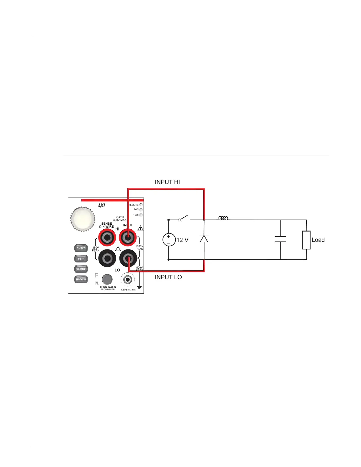
Device connections
The connections for the duty cycle test are shown in the figure below.
Figure 37: Duty cycle device connections
北京海洋兴业科技股份有限公司(证券代码:839145)