14
Kemppi Oy
4. SERVICE INSTRUCTIONS
4.1. Measurements and tests
Master has only few measurements that can be done because control circuitry is integrated to Z001 card
and panel does have only potentiometer and few press buttons.
4.1.1. Z001 Main circuit card
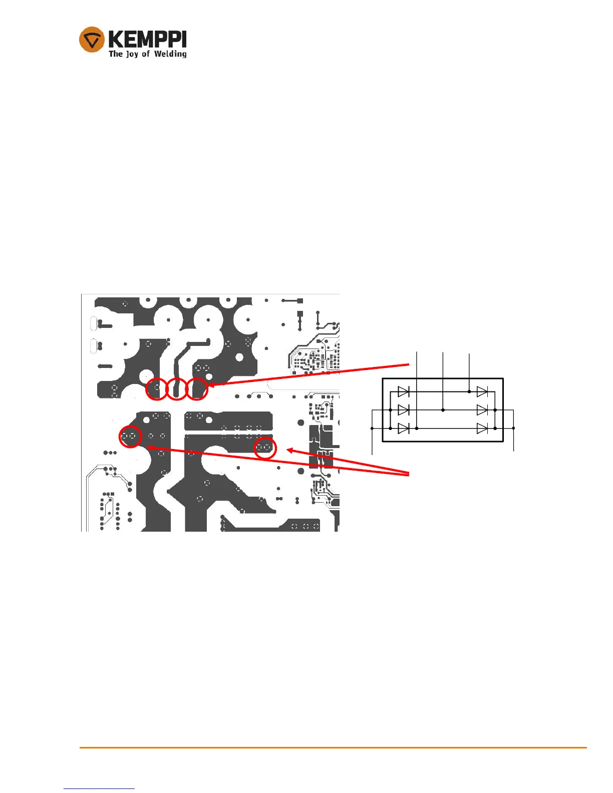
4.1.1.1. Primary rectifier
Supply voltage must not be connected during the block diode measuring.
Check the diode module using a multimeter diode function to measure its threshold voltage. Diodes must
be measured both forward bias and reverse bias condition to make sure they are fully functional. See the
picture above.
4.1.1.2. IGBT
Mains supply voltage must not be connected during the IGBT module diode measuring.
IGBT module can be tested by a multimeter when using the diode tester function. The module holds 4
IGBTs and diodes in parallel with IGBT. Typically these diodes fail or cannot be measured if IGBT module
is broken.

 Loading...