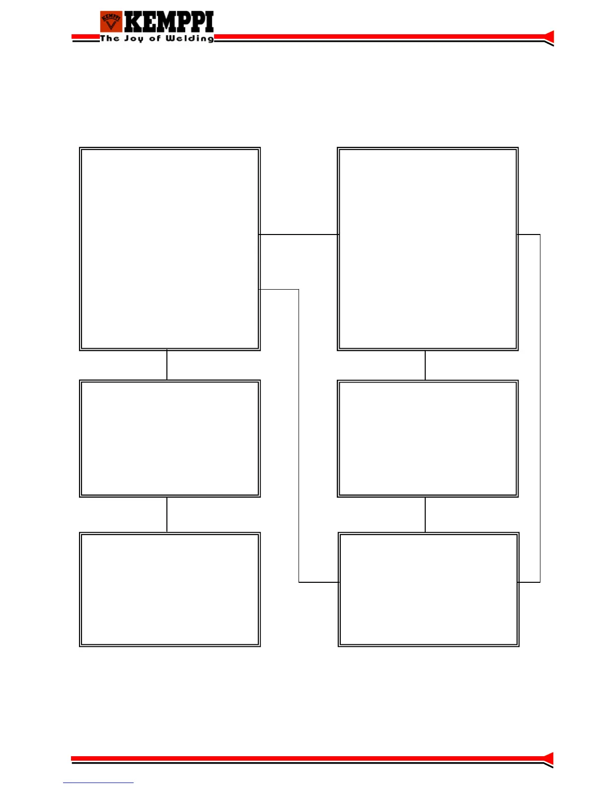
Block diagram
Control card A001
•Microcontroller
•PWM circuit
•Secondary voltage measurement
•Secondary current measurement
•IGBT driver
•Auxiliary device connection
•Auxiliary power supply
•Machine size jumpers
(J1, J2)
•Primary current limit jumpers(J3, J4, J5)
•Operational jumpers
•LED’s
•Water cooler connection
Control card A002
•WF-motor control
•Connection to the panel card P001
•Remote controller connection
•MIG gun connection
•Solenoid valve connection
•Fuse
Main circuit card Z001
•EMI filtering
•Three phase rectifier (V6)
•Switching-ON transient suppression
•Power Stage
•Current transformer (T1)
Capasitor card Z002
•Energy storage
•Discharging
Panel card P001
•Main micro controller
•User interface (buttons,
potentiometers, displays, LED’s)
•Connection to the A002
Secondary card Z003
•Rectifying
•Snubber
•Protection against HF
13
 Loading...