Product Manuals/Man-1088_Sigma XT_26 Page 12 of 40
5. Connecting to the circuit board
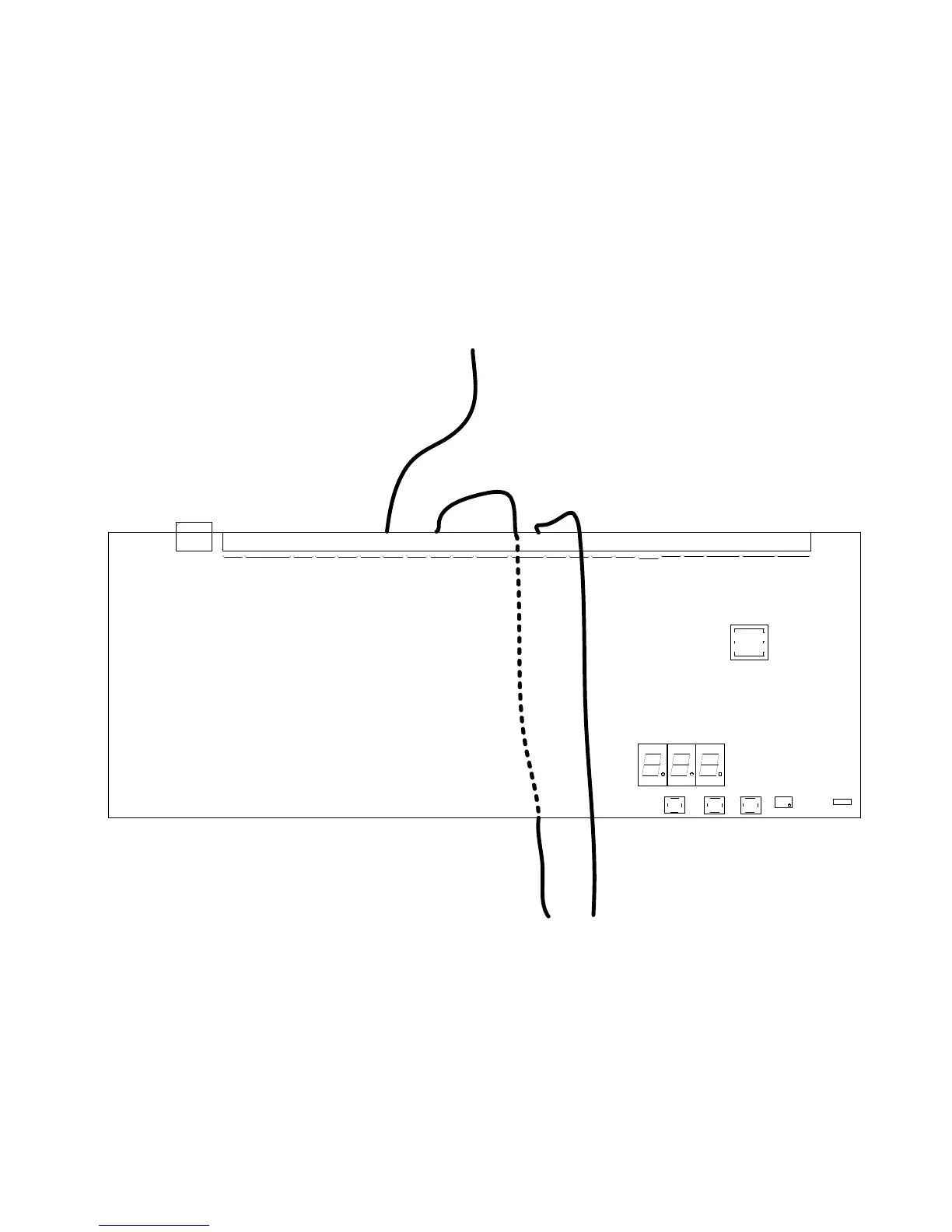
All connections for field wiring are to a single row of terminals along the top of the circuit board.
Shielded fire alarm cable such as FP200 and metal cable glands must be used for all connections
to the panel. The resistance of any core of any cable must not exceed 25 ohms. The shield of the
cable must be bonded securely to the enclosure via the metal gland.
Wiring should enter the enclosure at the top or back of the panel using the knockouts provided
and be formed tidily to the appropriate terminals.
Terminals are capable of accepting wires of up to 2.5mm
2
.
Wiring must not go across the front of the circuit board. If cable entries need to be in positions
other than at the knockouts provided, wiring must be fed behind and well away from the surface of
the circuit board.
The space at the bottom of the enclosure is largely occupied by the standby batteries so this must
be borne in mind when considering cable entries.
Figure 5 Wiring to the circuit board
SW1 4
SW 11
SW 1 0
SW 1 2
X1
X2
VR2
DI G0 DI G1 DI G2
SW13
MA N .
RELE ASE
EXTINGUISHANT
2ND STAGE
CON.
1ST S TAGE
CON.
FL OO D IN G
ZON E FLT.
MA N U A L
ONLY
AUTO
& MANUAL
EXTRACT
FA N
ENTERSELECTMOD ELAMP TEST
RES ET
ALARM/ FAULT
WARNING
SILENCE
AILENCE/SOUND
ALARM
EXT.
RELEASED
REL.
IMMIN ENT
1ST S TAGE
ACT.
HOLD
ACTIVATED
123
FIRE IN ZONE
GEN ERA L
FA UL T
POWER
FA UL T
SYSTEM
FA UL T
SOUNDER FAULT
/DISA BLEMENT
ALARM/FAULT
WARNING SILENCED
DELA Y ON
GE N ERA L
DISABLEMENT
TEST MODE
ON
POWER ON
MAINS
FAIL
BATT .
FAIL
CPU
FAULT
AUX 24 V
FAULT
BAT T.
LOW
COM M S
FAULT
EARTH
FAULT
SYS. F USE
FAULT
S1
FAULT
S2
FAULT
EXTING
FAULT
HOL D
FAULT
MAN. REL.
FAULT
MODE
FAULT
REL EA SE
FAULT
LOW PRES.
FAULT
TELL
TALE
EXTING
W/DOG
RES ET RES ET
WRITE
ENABLE
RELA SE
MAN U A L
PROC.
TE RM I NA TE
ZON E FAULT/TEST
/D IS ABL EMEN T
+
E
-
ROV
+
SIL
AL FLT RST
+
-
+
-
+
-
+
-
+
-
+
-
+
-
+
-
NC C
NO
NC C
NO
+
-
+
-
+
-
+
-
+
-
NC
CNCC
NO
NC C
NO
NC C
NO
+
-
FIRE RLYLOCAL FIREFAULT RLYEXTRACTLOW
PRES.
SWITCH
EXTI NG
PRES.
SWI TCH
REL .HOL D
MAN.
RE L E A S E
MODE
SELECT
2ND STAGE1ST STAGE2ND
SOUNDE R
ZONE3ZONE1 ZONE2S2S1
1ST STAGE
SOUNDERS
POWERDAT A
STATUS UNITS
REM OT E CONTROL
AUX
24V
2ND STAGE
SNDR FAULT
FIR E
COMMON
LOW PRESSURE
CORRECT
INCORRECT
INCORRECT