Product Manuals/Man-1088_Sigma XT_26 Page 35 of 40
21. Maintenance
SIGMA XT control panels do not require any specific maintenance but should the control panel
become dirty it can be wiped over with a barely damp cloth. Detergents or solvents should not be
used to clean the panel and care must be taken that water does not enter the enclosure.
The control panel contains sealed lead acid batteries to provide standby power in the event of
mains failure.
These batteries have a life expectancy of around 4 years. It is recommended that these batteries
be tested in accordance with the battery manufacturer’s recommendations annually to determine
their suitability for continued standby applications.
Testing of the extinguishant system should only be carried out by trained personnel and must be
done with appropriate isolation measures in place to ensure that accidental discharge of the
extinguishant agent is avoided.
Should the control panel become faulty the complete electronic assembly and front plate can be
replaced.
To do this, any configured options should be noted then both mains and battery power should be
removed before the work is started.
The field wiring should be carefully labelled and removed from the terminals. The power terminal
block can be unplugged from the PCB by pulling it towards you.
The PCB can now be taken out of the panel by removing the 2 screws.
Fitting the new PCB is the reverse of the procedure for removing the board.
22. Record of configuration
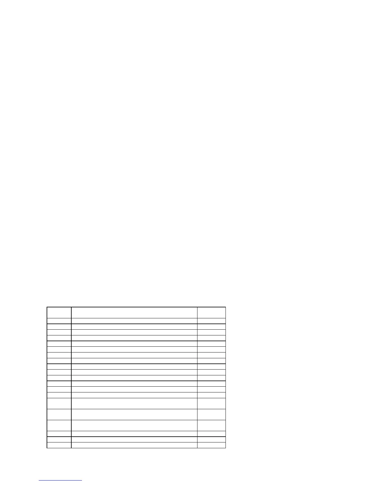
Use the table below to record the configuration codes that have been set on the control panel for
future reference. Place a tick in the box for any configuration options that are set.
It is recommended that a copy of this table is left with the control panel under the supervision of
the person responsible for the fire protection system.
NOTE: Setting the options marked with asterisks does not comply with EN54-2
CODE FUNCTION TICK SET
OPTIONS
C00 SOUNDER DELAY TIME = 30 SECONDS
C01 SOUNDER DELAY TIME = 1 MINUTE
C02 SOUNDER DELAY TIME = 2 MINUTES
C03 SOUNDER DELAY TIME = 3 MINUTES
C04 SOUNDER DELAY TIME = 4 MINUTES
C05 SOUNDER DELAY TIME = 5 MINUTES
C06 SOUNDER DELAY TIME = 6 MINUTES
C07 SOUNDER DELAY TIME = 7 MINUTES
C08 SOUNDER DELAY TIME = 8 MINUTES
C09 SOUNDER DELAY TIME = 9 MINUTES
C11 Z1 & Z2 DETECTORS TRIGGER AUTOMATIC RELEASE
C12 Z2 & Z3 DETECTORS TRIGGER AUTOMATIC RELEASE
C13 Z1 &Z3 DETECTORS TRIGGER AUTOMATIC RELEASE
C14 Z1 & Z2 OR Z2 & Z3 OR Z1 & Z3 DETECTORS TRGGER
AUTOMATIC RELEASE
*C15 Z1 & Z2 & Z3 DETECTORS TRIGGER AUTOMATIC
RELEASE
C16 Z1 OR Z2 OR Z3 DETECTORS TRIGGER AUTOMATIC
RELEASE
C17 Z1 DETECTORS TRIGGER AUTOMATIC RELEASE
C18 Z2 DETECTORS TRIGGER AUTOMATIC RELEASE
C19 Z3 DETECTORS TRIGGER AUTOMATIC RELEASE