Product Manuals/Man-1088_Sigma XT_26 Page 21 of 40
14.2 Removing status units/ancillary boards
When status units/ancillary boards are to be removed from the system, the system must be
powered down first and the status units/ancillary boards removed. The system should then be
powered. When the system starts it will be in fault and the units removed will be shown on the
display. Status units are shown as Fux and ancillary boards are shown as Fox (where x is the
address of the unit). The Select button can be used to view all of the status units/ancillary boards
that the system expects to be found but are now missing.
For the system to accept the removal of these devices from its memory the following procedure
must be carried out.
1. Operate the Enable Controls keyswitch.
2. Enable the Write Enable Switch (push to the right) – Access level 3.
3. Wait for the General fault LED to illuminate
4. Disable the Write enable switch (push to the left)
5. Disable the Enable controls keyswitch
6. The panel should return to the normal quiescent condition.
If the panel fails to receive messages from a status unit or ancillary board after it has been stored
in the configuration memory, the internal “comms fault” LED will light and a fault condition will be
displayed on the panel fascia. The seven segment display on the panel will show the number of
the unit that is disconnected and all LEDs on the status unit that is disconnected will flash.
Full details of status units and ancillary boards can be found in document K7247-02 (Sigma XT
Status unit and Ancillary board operation and maintenance manual).
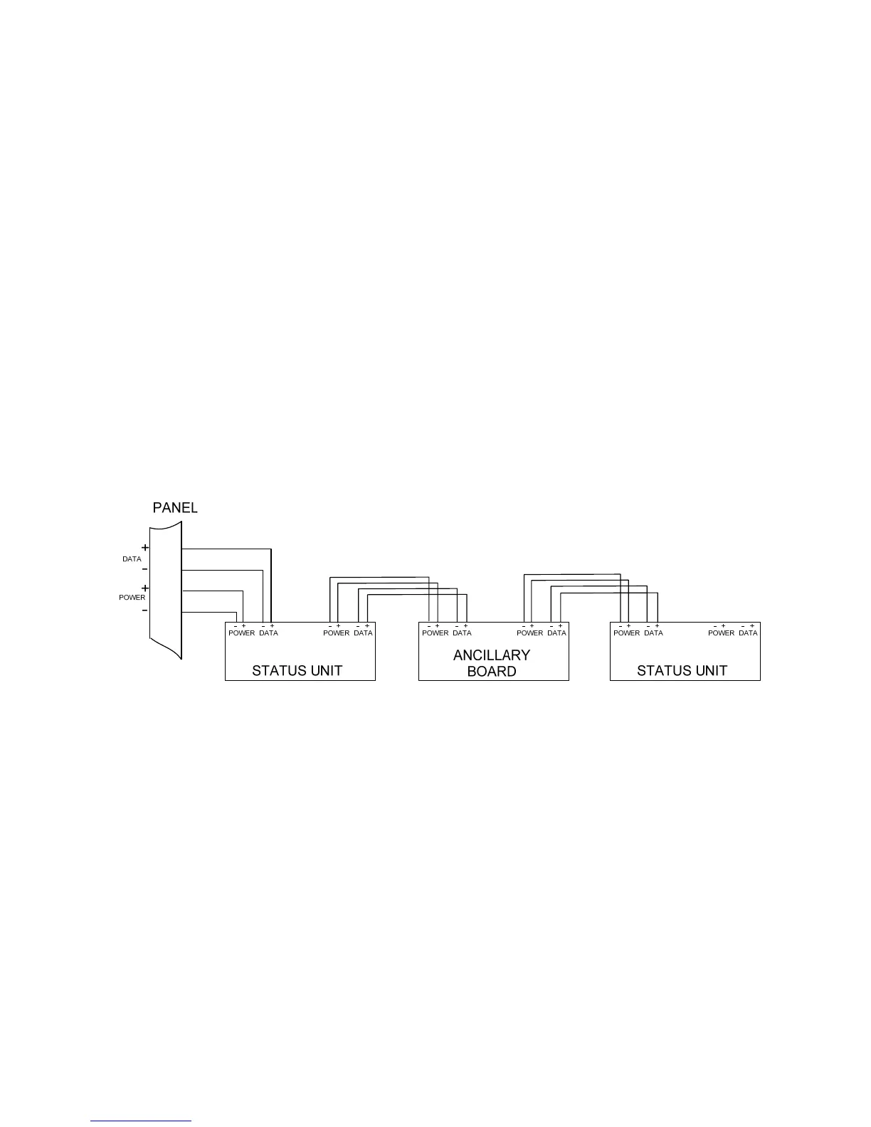
Figure 15. – Wiring to status units and ancillary boards
15. Panel operation
15.1 Normal condition
Under normal conditions, control panels will have only the green, Power On LED lit and either the
Manual Only or Automatic and Manual LED lit. The display will be blank.
The control panel has 3 access levels. Access level 1 allows unrestricted access, Access level 2
allows access only after operation of the front panel mounted “Enable controls” keyswitch and
Access level 3 allows access after operation of the “Write enable” switch behind the front cover.
15.2 Single zone Fire condition
Upon receipt of a fire condition by activation of a detector or call point, the Common Fire indicator
will light and the zonal Fire indicators will flash at around 2Hz.
The fire and local fire relays will also operate and signal any systems to which they are connected.
Any sounders connected to the sounder circuits S1 & S2 will operate.
If the zone that has activated is contributing to the extinguishant release sequence, the First stage
activated LED will light and the first stage relay contact will operate.