Product Manuals/Man-1088_Sigma XT_26 Page 31 of 40
19. Internal indications – troubleshooting
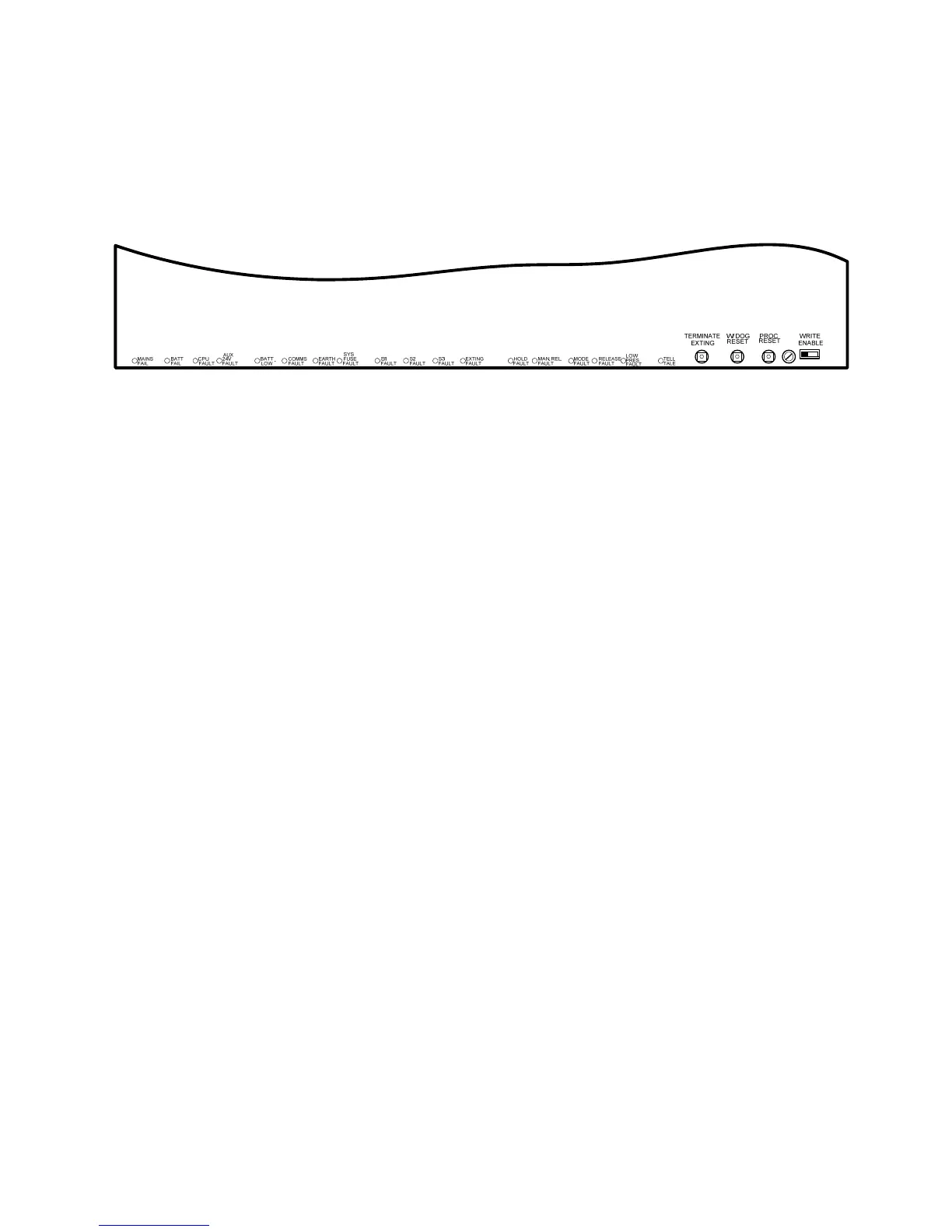
To assist in identifying fault conditions which are not detailed on the front of the control panel, a
number of internal indicators are visible with the front cover removed as follows:
Figure 19. Internal fault LED
19.1 Mains fail
Indicates that the 230V AC supply is not present and the system is running on standby batteries.
If there is not a power cut, check the panels mains fuse.
19.2 Batt fail
Indicates that the standby battery has become disconnected or that the charging circuit of the
control panel has failed. Check that both batteries are connected and linked together. Test battery.
Disconnect battery and ensure that 28 Volts can be measured on battery charger leads.
19.3 CPU fault
Indicates that the central processor unit has failed to correctly execute code and has been re-
started by the system watchdog. The watchdog reset switch must be pressed to clear the CPU
fault condition.
Press watchdog reset. If system does not return to normal then the panel is probably damaged
and needs the circuit board replacing. (See maintenance section 21).
19.4 Aux 24V fault
The Aux 24V and R0V terminals provide a 500 milliamp, 24V DC power supply for power fire
alarm ancillary equipment. This LED indicates that fuse protecting the R0V output has operated
and the rating of this output has been exceeded. The fuse is a self resetting type and the supply
will resume when the fault condition is removed.
19.5 Batt low
Illuminates when the system is running on batteries and the battery voltage is between 21.5 V and
20.5 V (the minimum battery voltage).
19.6 Comms fault
Indicates that communication has been lost with a repeater panel or Ancillary board. Check for
comms fault at all repeaters and ancillary boards to identify the source of the problem.
The comms fault LED will be accompanied by the front panel Flooding zone fault LED to indicate a
common fault condition within the extinguishant section of the control panel.