OPERATION
INITIAL STARTING PROCEDURE
Until you familiarize yourself with the use of all controls,
the following procedure may be used to standarize the in-
itial setting of controls as a reference point and to obtain
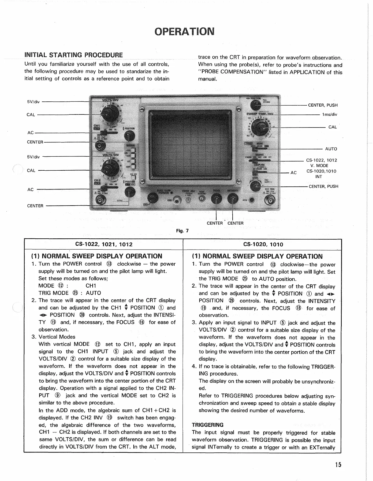
trace on the CRT in preparation for waveform observation.
When using the probe(s), refer to probe's instructions and
"PROBE COMPENSATION" listed in APPLICATION of this
manual.
CS-1022, 1021, 1012
CS-1020, 1010
(1)
NORMAL SWEEP DISPLAY OPERATION
1.
Turn the POWER control © clockwise — the power
supply will be turned on and the pilot lamp will light.
Set these modes as follows;
MODE © : CH1
TRIG MODE © : AUTO
2.
The trace will appear in the center of the CRT display
and can be adjusted by the CH1 • POSITION © and
o
POSITION ® controls. Next, adjust the INTENSI-
TY © and, if necessary, the FOCUS © for ease of
observation.
3. Vertical Modes
With vertical MODE © set to CH1, apply an input
signal to the CH1 INPUT (5) jack and adjust the
VOLTS/DIV (2) control for a suitable size display of the
waveform. If the waveform does not appear in the
display, adjust the VOLTS/DIV and y POSITION controls
to bring the waveform into the center portion of the CRT
display. Operation with a signal applied to the CH2 IN-
PUT (D jack and the vertical MODE set to CH2 is
similar to the above procedure.
In the ADD mode, the algebraic sum of CH1 +CH2 is
displayed.
If the CH2 INV © switch has been engag-
ed,
the algebraic difference of the two waveforms,
CH1 — CH2 is displayed. If both channels are set to the
same VOLTS/DIV, the sum or difference can be read
directly in VOLTS/DIV from the CRT. In the ALT mode,
(1)
NORMAL SWEEP DISPLAY OPERATION
1.
Turn the POWER control © clockwise—the power
supply will be turned on and the pilot lamp will light. Set
the TRIG MODE © to AUTO position.
2.
The trace will appear in the center of the CRT display
and can be adjusted by the y POSITION 0 and
POSITION © controls. Next, adjust the INTENSITY
® and, if necessary, the FOCUS © for ease of
observation.
3. Apply an input signal to INPUT © jack and adjust the
VOLTS/DIV (2) control for a suitable size display of the
waveform. If the waveform does not appear in the
display, adjust the VOLTS/DIV and v POSITION controls
to bring the waveform into the center portion of the CRT
display.
4.
If no trace is obtainable, refer to the following TRIGGER-
ING procedures.
The display on the screen will probably be unsynchroniz-
ed.
Refer to TRIGGERING procedures below adjusting
syn-
chronization and sweep speed to obtain a stable display
showing the desired number of waveforms.
TRIGGERING
The input signal must be properly triggered for stable
waveform observation. TRIGGERING is possible the input
signal INTernally to create a trigger or with an EXTernally
15
Fig.
7