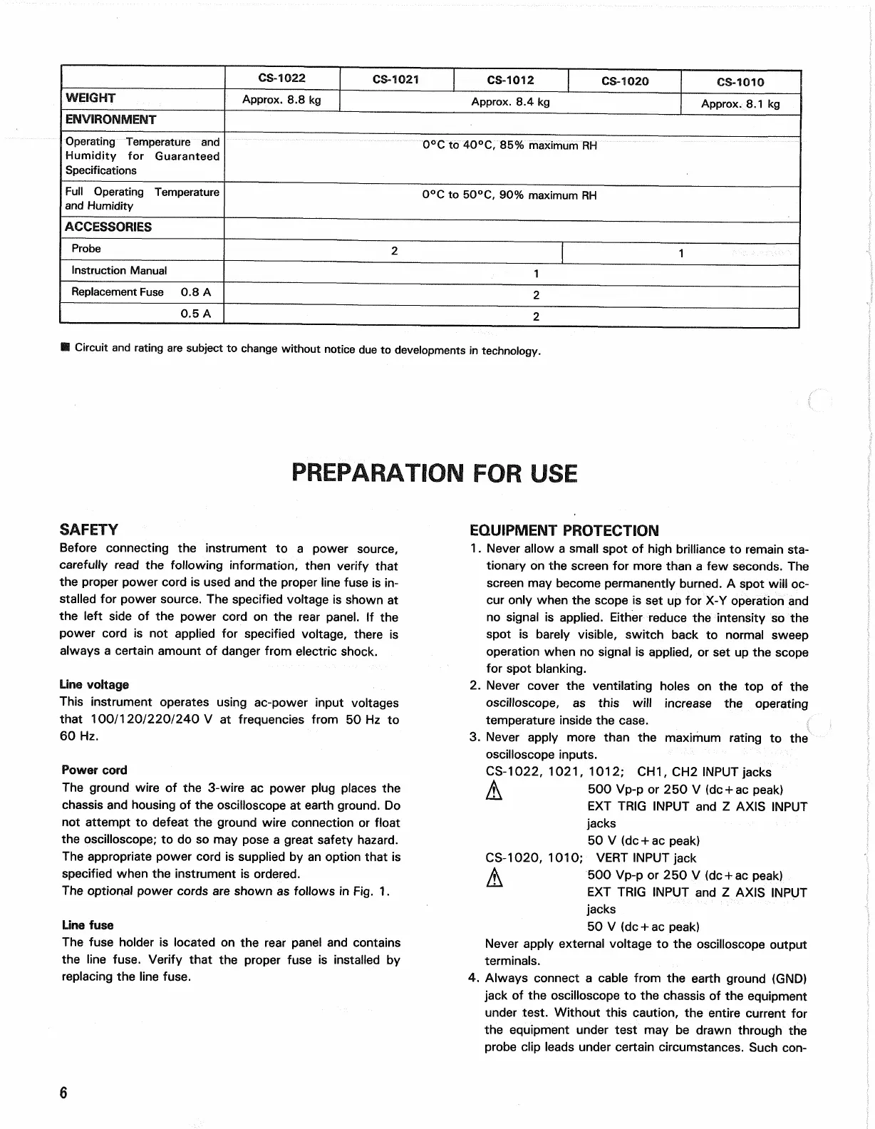
CS-1022
CS-1021 CS-1012
CS-1020
CS-1010
WEIGHT
Approx. 8.8 kg
Approx. 8.4 kg
Approx. 8.1 kg
ENVIRONMENT
Operating Temperature and
Humidity for Guaranteed
Specifications
0°C to 40°C, 85% maximum RH
Full Operating Temperature
and Humidity
0°C to 50°C, 90% maximum RH
ACCESSORIES
Probe
2
1
Instruction Manual
1
Replacement Fuse 0.8 A
2
0.5 A
2
• Circuit and rating are subject to change without notice due to developments in technology.
PREPARATION FOR USE
SAFETY
Before connecting the instrument to a power source,
carefully read the following information, then verify that
the proper power cord is used and the proper line fuse is in-
stalled for power source. The specified voltage is shown at
the left side of the power cord on the rear panel. If the
power cord is not applied for specified voltage, there is
always a certain amount of danger from electric shock.
Line voltage
This instrument operates using ac-power input voltages
that 100/120/220/240 V at frequencies from 50 Hz to
60 Hz.
Power cord
The ground wire of the 3-wire ac power plug places the
chassis and housing of the oscilloscope at earth ground. Do
not attempt to defeat the ground wire connection or float
the oscilloscope; to do so may pose a great safety hazard.
The appropriate power cord is supplied by an option that is
specified when the instrument is ordered.
The optional power cords are shown as follows in Fig. 1.
Line fuse
The fuse holder is located on the rear panel and contains
the line fuse. Verify that the proper fuse is installed by
replacing the line fuse.
EQUIPMENT PROTECTION
1.
Never allow a small spot of high brilliance to remain sta-
tionary on the screen for more than a few seconds. The
screen may become permanently burned. A spot will oc-
cur only when the scope is set up for X-Y operation and
no signal is applied. Either reduce the intensity so the
spot is barely visible, switch back to normal sweep
operation when no signal is applied, or set up the scope
for spot blanking.
2.
Never cover the ventilating holes on the top of the
oscilloscope, as this will increase the operating
temperature inside the case.
3. Never apply more than the maximum rating to the
oscilloscope inputs.
CS-1022, 1021, 1012; CH1, CH2 INPUT jacks
500 Vp-p or 250 V (dc + ac peak)
EXT TRIG INPUT and Z AXIS INPUT
jacks
50 V (dc + ac peak)
CS-1020, 1010; VERT INPUT jack
A 500 Vp-p or 250 V (dc + ac peak)
EXT TRIG INPUT and Z AXIS INPUT
jacks
50 V (dc + ac peak)
Never apply external voltage to the oscilloscope output
terminals.
4.
Always connect a cable from the earth ground (GND)
jack of the oscilloscope to the chassis of the equipment
under test. Without this caution, the entire current for
the equipment under test may be drawn through the
probe clip leads under certain circumstances. Such con-
6