TIME MEASUREMENTS
This is the procedure for making time measurements be-
tween two points on a waveform. The combination of the
SWEEP TIME/DIV and the horizontal distance in divisions
between the two points is used in the calculation.
Procedure:
1.
Apply the signal to be measured to the INPUT jack. Set
the vertical MODE to the channel to be used (unapplied
to CS-1020 and 1010). Adjust the VOLTS/DIV and
SWEEP TIME/DIV for a normal display.
Be sure that the VARIABLE control is set to CAL.
2.
Using the • POSITION control, set one of the points to
be used as a reference to coincide with the horizontal
centerline. Use the < • POSITION control to set this
point at the intersection of any vertical graduation line.
3. Measure the horizontal distance between the two
points.
Multiply this by the setting of the SWEEP TIME/DIV
con-
trol to obtain the time between the two points. If
horizontal " x 10 MAG " is used, multiply this further by
1/10.
Using the formula:
Time = Horizontal distance (div)x (SWEEP TIME/DIV set-
ting) x"x 10 MAG" value
1
(1/10)
[EXAMPLE]
For the example, the horizontal distance between the two
points is 5.4 divisions.
If the SWEEP TIME/DIV is 0.2 ms/div we calculate. (See
Fig.
14)
Substituting the given value:
Time = 5.4 (div) x 0.2 (ms) = 1.08 ms
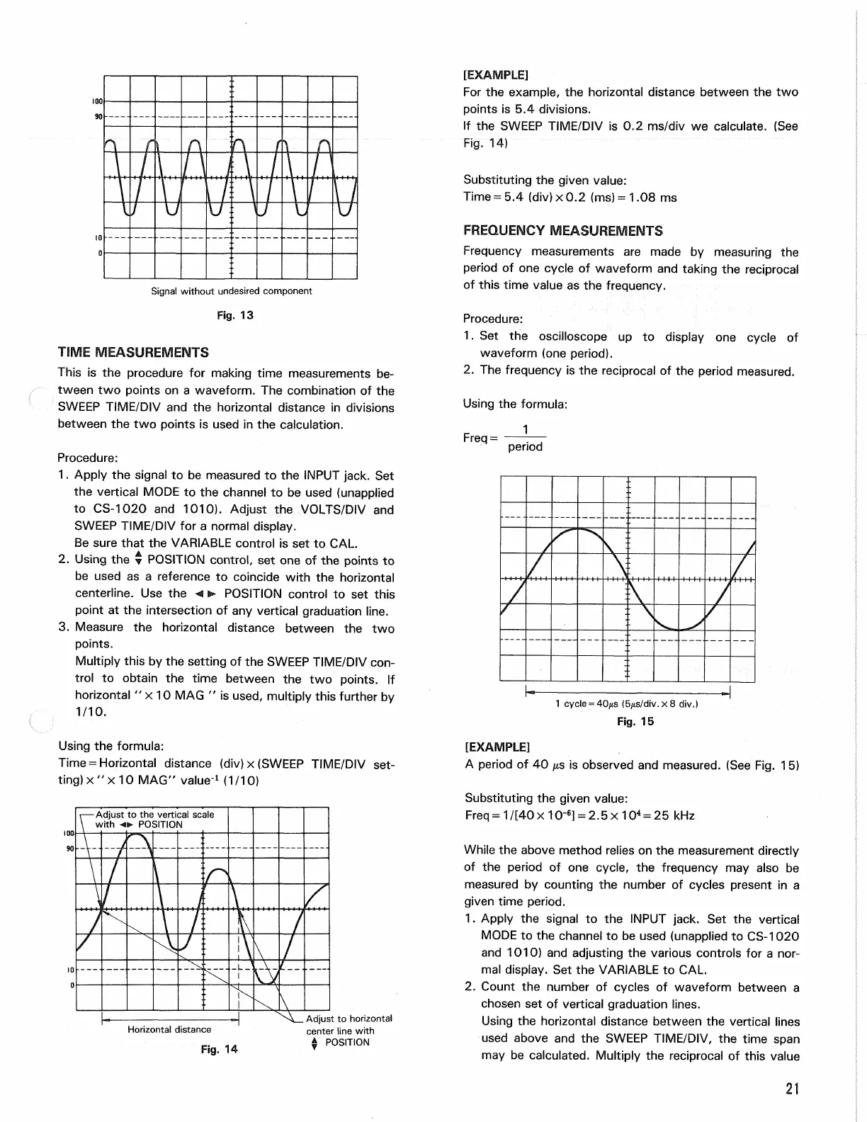
FREQUENCY MEASUREMENTS
Frequency measurements are made by measuring the
period of one cycle of waveform and taking the reciprocal
of this time value as the frequency.
Procedure:
1.
Set the oscilloscope up to display one cycle of
waveform (one period).
2.
The frequency is the reciprocal of the period measured.
Using the formula:
Freq= 1
period
Adjust to horizontal
center line with
POSITION
[EXAMPLE]
A period of 40 us is observed and measured. (See Fig.
1
5)
Substituting the given value:
Freq=1/[40x10"
6
] = 2.5x10
4
= 25 kHz
While the above method relies on the measurement directly
of the period of one cycle, the frequency may also be
measured by counting the number of cycles present in a
given time period.
1.
Apply the signal to the INPUT jack. Set the vertical
MODE to the channel to be used (unapplied to CS-1020
and 1010) and adjusting the various controls for a nor-
mal display. Set the VARIABLE to CAL.
2.
Count the number of cycles of waveform between a
chosen set of vertical graduation lines.
Using the horizontal distance between the vertical lines
used above and the SWEEP TIME/DIV, the time span
may be calculated. Multiply the reciprocal of this value
21
Signal without undesired component
Fig.
13
Fig.
15
1 cycle = 40/*s (5/*s/div.x8 div.)
Adjust to the vertical scale
with POSITION
Horizontal distance
Fig.
14