MEASUREMENT OF THE VOLTAGE BETWEEN TWO
POINTS ON
A
WAVEFORM
This technique
can be
used
to
measure peak-to-peak
voltages.
Procedure:
1.
Apply
the
signal
to be
measured
to the
INPUT jack.
Set
the vertical MODE
to the
channel
to be
used (unapplied
to CS-1020
and
1010).
Set the
AC-GND-DC
to
AC,
ad-
justing VOLTS/DIV
and
SWEEP TIME/DIV
for a
normal
display.
Set the
VARIABLE
to CAL.
2.
Using
the y
POSITION control, adjust
the
waveform
position such that
one of the two
points falls
on a CRT
graduation line
and
that
the
other
is
visible
on the
display screen.
3. Using
the
POSITION control, adjust
the
second
point
to
coincide with
the
center vertical graduation line.
4.
Measure
the
vertical distance between
the two
points
and multiply this
by the
setting
of the
VOLTS/DIV
con-
trol.
If
a
probe
is
used, further multiply this
by the
attenua-
tion ratio.
Using
the
formula:
Volts Peak-to-Peak
= Vertical distance (div)
x
(VOLTS/DIV setting)
x
(probe
attenuation ratio)
Adjust
to the
center
vertical scale with
ELIMINATION OF UNDESIRED SIGNAL
COMPONENTS (Unapplied
to
CS-1020
and
1010)
The
ADD
feature
can be
conveniently used
to
cancel
out
the effect
of an
undesired signal component which
superimposed
on the
signal
you
wish
to
observe.
Procedure:
1.
Apply
the
signal containing
an
undesired component
to
the CH1 INPUT jack and
the
undesired signal itself alone
to
the CH2
INPUT jack.
2.
Set the
vertical MODE
to
CHOP
and
SOURCE
to CH2.
Verify that
CH2
represents
the
unwanted signal
in
reverse polarity.
If
necessary reverse polarity
by
setting
CH2
to INV.
3.
Set the
vertical MODE
to
ADD, SOURCE
to V.
MODE
and
CH2
VOLTS/DIV
and
VARIABLE
so
that
the
undesired signal component
is
cancelled
as
much
as
possible.
The
remaining signal should
be the
signal
you
wish
to
observe alone
and
free
of the
unwanted signal.
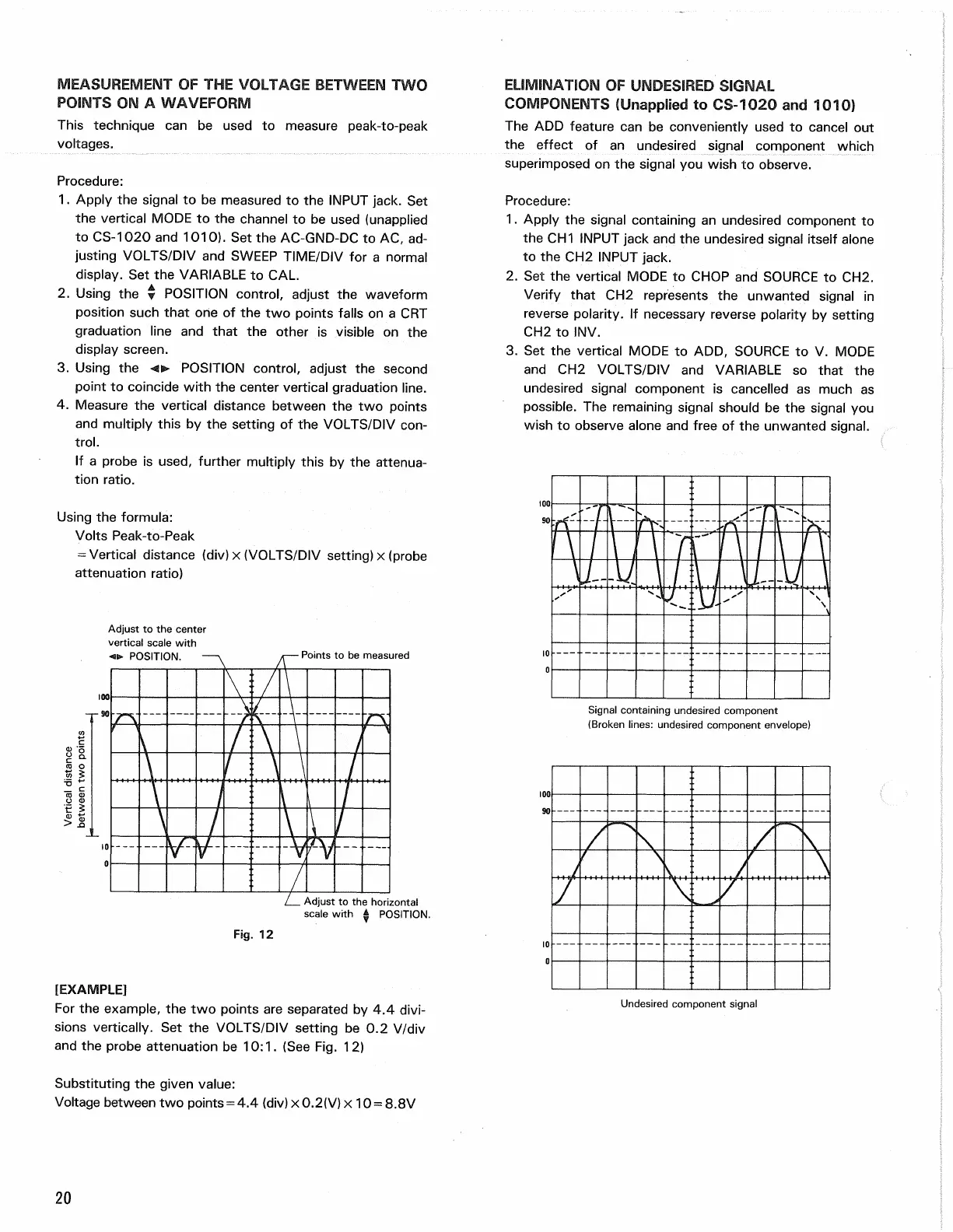
Signal containing undesired component
(Broken lines: undesired component envelope)
20
Vertical distance
between two
points
Points
to be
measured
Fig.
12
Adjust
to the
horizontal
scale with POSITION.
[EXAMPLE]
For
the
example,
the two
points
are
separated
by 4.4
divi-
sions vertically.
Set the
VOLTS/DIV setting
be 0.2
V/div
and
the
probe attenuation
be
10:1.
(See
Fig.
12)
Substituting
the
given value:
Voltage between
two
points
=
4.4 (div)x0.2(V)x 10
=
8.8V
Undesired component signal