CS-1022.
1021. 1012
CS-1020,
1010
signal being observed to synchronize the display. External
sync is prefered for waveform observation in many applica-
tions.
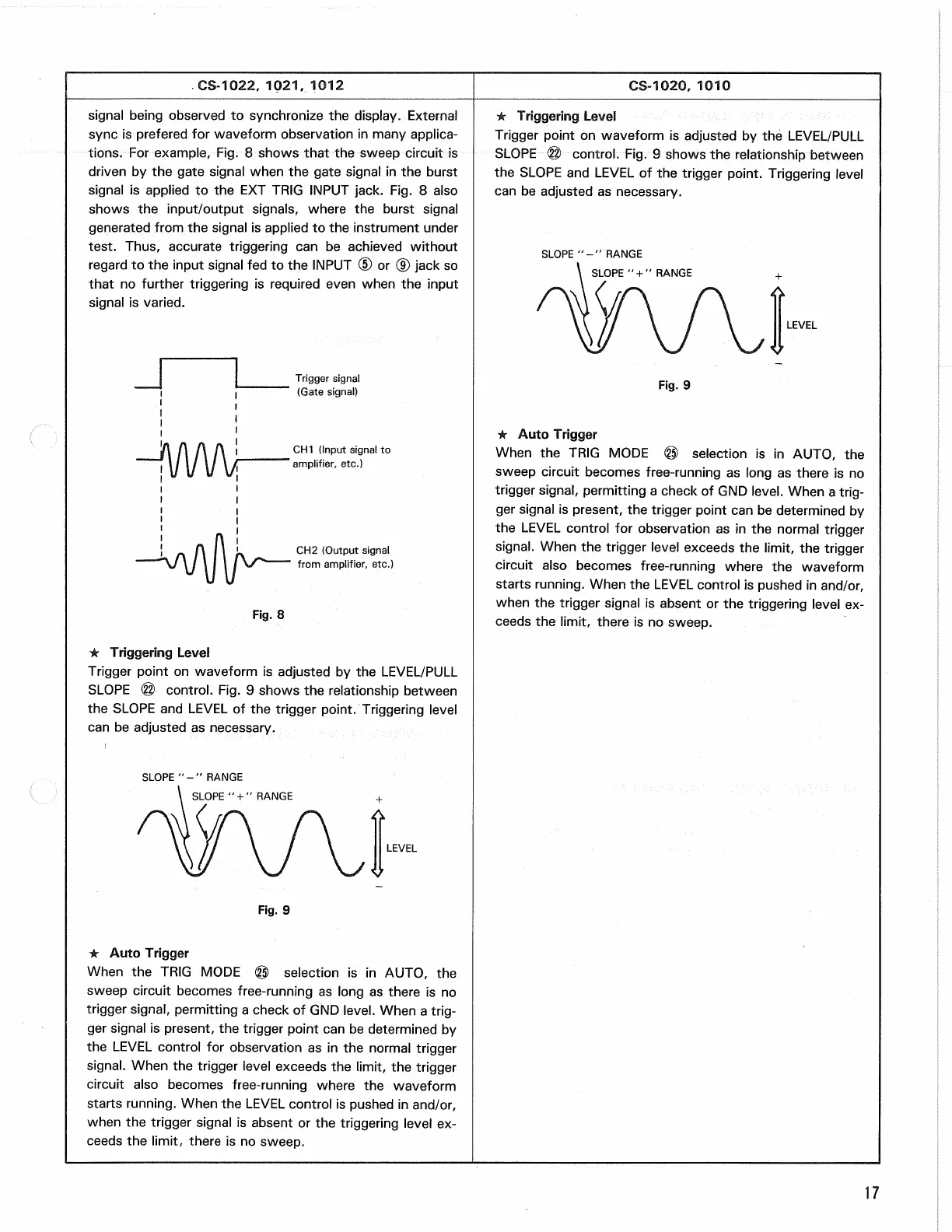
For example, Fig. 8 shows that the sweep circuit is
driven by the gate signal when the gate signal in the burst
signal is applied to the EXT TRIG INPUT jack. Fig. 8 also
shows the input/output signals, where the burst signal
generated from the signal is applied to the instrument under
test. Thus, accurate triggering can be achieved without
regard to the input signal fed to the INPUT (D or (9) jack so
that no further triggering is required even when the input
signal is varied.
Trigger signal
(Gate signal)
CH1
(Input signal
to
'
amplifier,
etc.)
CH2
(Output signal
from
amplifier,
etc.)
* Triggering Level
Trigger point on waveform is adjusted by the LEVEL/PULL
SLOPE @ control. Fig. 9 shows the relationship between
the SLOPE and LEVEL of the trigger point. Triggering level
can be adjusted as necessary.
• Triggering Level
Trigger point on waveform is adjusted by the LEVEL/PULL
SLOPE ® control. Fig. 9 shows the relationship between
the SLOPE and LEVEL of the trigger point. Triggering level
can be adjusted as necessary.
LEVEL
* Auto Trigger
When the TRIG MODE © selection is in AUTO, the
sweep circuit becomes free-running as long as there is no
trigger signal, permitting a check of GND
level.
When a
trig-
ger signal is present, the trigger point can be determined by
the LEVEL control for observation as in the normal trigger
signal.
When the trigger level exceeds the limit, the trigger
circuit also becomes free-running where the waveform
starts running. When the LEVEL control is pushed in and/or,
when the trigger signal is absent or the triggering level ex-
ceeds the limit, there is no sweep.
LEVEL
Fig.
9
* Auto Trigger
When the TRIG MODE © selection is in AUTO, the
sweep circuit becomes free-running as long as there is no
trigger signal, permitting a check of GND
level.
When a
trig-
ger signal is present, the trigger point can be determined by
the LEVEL control for observation as in the normal trigger
signal.
When the trigger level exceeds the limit, the trigger
circuit also becomes free-running where the waveform
starts running. When the LEVEL control is pushed in and/or,
when the trigger signal is absent or the triggering level ex-
ceeds the limit, there is no sweep.
17
SLOPE
"-"
RANGE
SLOPE
" + "
RANGE
Fig.
9
Fig.
8
SLOPE
"-"
RANGE
SLOPE
" + "
RANGE